097-10603-01 Rev. A – November 2004 X72 Desiger’s Reference and User’s Guide 83
Setting the X72 for 1PPS Synchronization
The “j” Command
Press the j key at any time to return the current value in hex format from the Delta
Register see Note 1, on page 84) as well as the 1PPS state see Note 2, on page 84
below and the following table). The output format appears similar to the following:
r>j
Delta Reg: 39386F5 1ppsState:6
See X72 1PPS Algorithm Theory of Operation, on page 87 for additional information
on 1PPS states.
The “g” Command
The “g” command allows you to change the X72 to operate in any of three modes
which affect the output of the Lock Pin (pin 21). Note that this 1PPS mode can be
changed by the user but cannot be saved. If power is cycled to the unit it reverts to
the factory default. The modes are:
0 = 1PPS Disciplining Disabled – Normal Rb Lock Pin functionality. Only the
Rb loop needs to be locked to indicate a locked condition on pin 21.
1 = 1PPS Disciplining Enabled – Normal Lock Pin functionality. Only the Rb
loop needs to be locked to indicate a locked condition on pin 21.
2 = 1PPS Disciplining Enabled – Requires both Rb loop to be locked AND
1PPS synchronization lock to indicate a locked condition on pin 21.
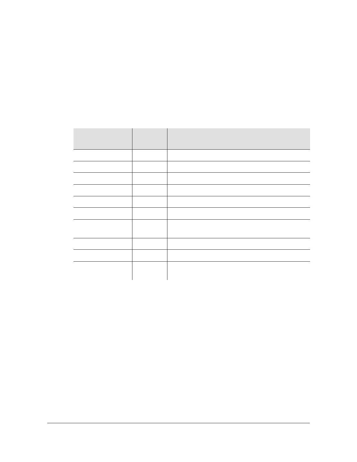
Table D-1. 1PPS States Returned with the j Command
Description
Expected
Values
Action Being Performed
INITIALIZE0STATE 0 Start up initialization
INITIALIZE1STATE 1 Start up initialization
INITIALIZE2STATE 2 Start up initialization
HOLDOVERSTATE 3 Seeking usable 1PPS
JAMSYNC1STATE 4 Synch X72 output 1PPS to input
JAMSYNC2STATE 5 Synch X72 output 1PPS to input
DISCIPLINESTATE 6 Keep X72 output 1PPS aligned to input by
controlling X72 frequency
PIDCALCSTATE 7 Calculations for disciplining algorithm
PDATEDDSSTATE 8 Update X72 DDS based on PIDCALCSTATE output.
ALCSLOPESTATE 9 Calculate slope of incoming 1PPS vs. X72 1PPS
during holdover.
 Loading...