3 Installation Procedure
Zones
16 The PDRP-1001 PN 50734:C 03/11/99
Initiating Device Circuits
Zones
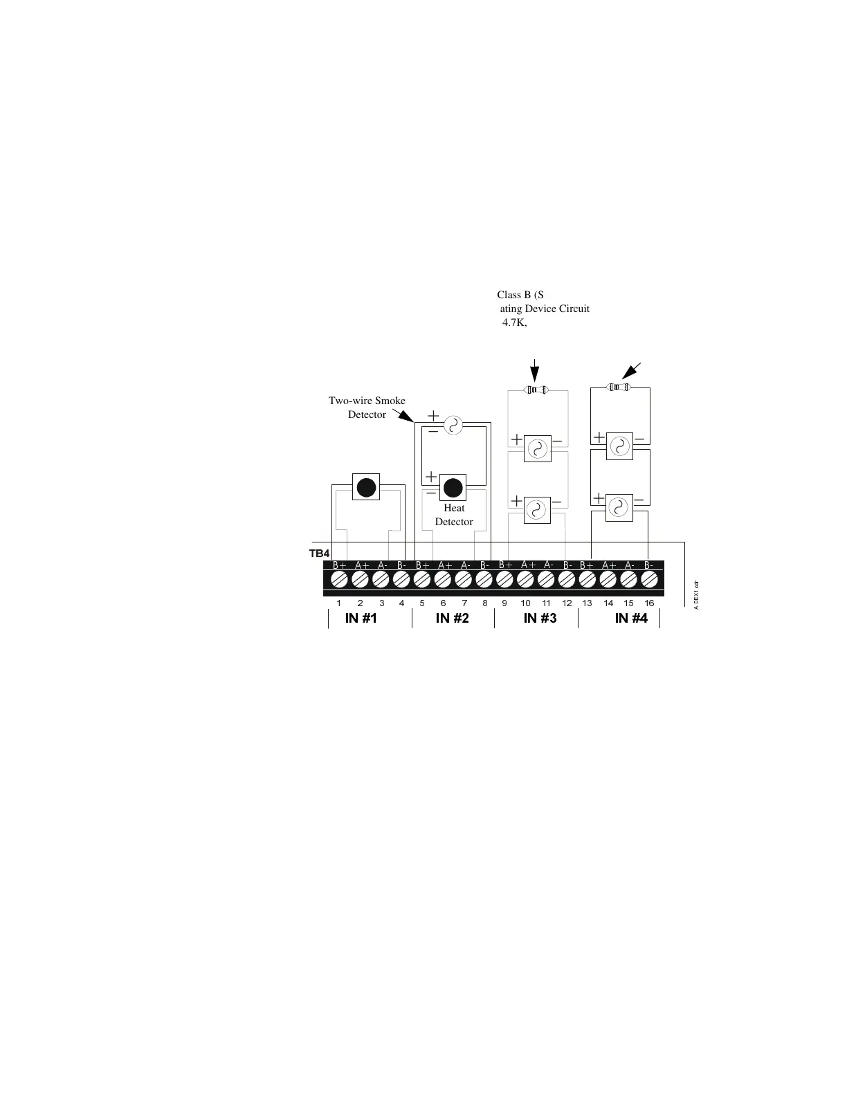
Wire all alarm initiating devices sequentially for proper supervision. Initiating devices
include: heat, photoelectric, and ionization type detectors; and waterflow alarm
devices. Refer to the Compatibility Chart in Appendix B.
Note:
• Observe polarity when connecting polarized devices.
• All circuits are supervised and power limited.
• Leave Dummy Load (provided) on all unused circuits.
Figure 4 Example of an Alarm Initiating Device
Heat
Detector
Two-wire Smoke
Detector
Class B (Style B)
Initiating Device Circuit
4.7K, 1/2-Watt
(NOTIFIER part # 71252
UL listed)
Class A (Style D)
Initiating Device
Circuit
Manual Release
Class B (Style B)
Supervisory Circuit
4.7K, 1/2-Watt
(NOTIFIER part # 71252
UL listed)
Normally Open
Waterflow Devices
or Pressure
Switches
Normally Open
Tamper Switches or
Pressure Switches