For Remote Station Service
1 The PDRP-1001/PDRP-1001A/PDRP-1001E
The PDRP-1001 PN 50734:C 03/11/99 9
Trip current: 0.35 amps. (Subtracted from Notification Appliance power)
Coil Voltage: 3.65 VDC
Coil resistance: 14.6 ohms
Maximum allowable wire resistance between panel and trip coil: 3 ohms
Municipal Box wiring can leave the building
For Remote Station Service
(NFPA 72 Remote Station Fire Alarm System):
Maximum load for each circuit: 10mA
Reverse polarity output voltage: 24 VDC
Remote Alarm and Remote Trouble wiring can leave the building
LED Interface Module (4XLM - NOTIFIER)
Maximum voltage/current, each output: 27.6V/8mA
Note: Outputs are power limited
Zone Relay Module (4XZM - NOTIFIER)
Dry Form-C contacts rated: 2.0 amps @ 30VDC (resistive), 0.5 amps @ 30 VAC
(resistive)
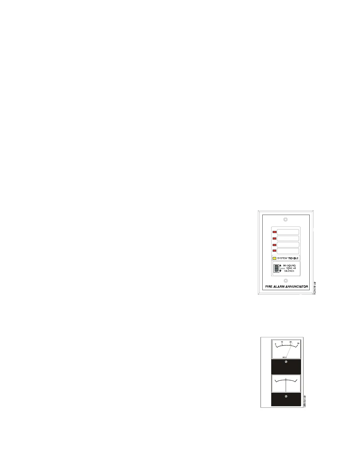
Remote Annunciator
Remote Annunciator (RZA-4X - NOTIFIER)
The Remote Annunciator mounts on a standard single-
gang box, and provides LED indication of the following:
• Alarm/Waterflow Bell (red)
• Waterflow/Supervisory Bell (red)
• Releasing Circuit 1 (red)
• Supervisory Bell/Release Circuit 2 (red)
• System Trouble LED (yellow)
A Local Trouble Sounder and Silence Switch are also
provided. All LED wiring is supervised for open
conditions. Any open condition will cause the System
Trouble LED to illuminate.
Note: The Remote Annunciator requires the use of an LED Interface module (4XLM).
Optional Meters
Voltage, Current Meters (4XMM - NOTIFIER)
The Meter Module provides a voltmeter to measure the
voltage across the batteries and an ammeter to measure
the charging current to the batteries. The meters are
provided as an assembly that mounts to the lower left-
hand corner of the cabinet.
0
10
20
30
DC VOLTS
0
5
5
DC AMPERES