EasyManuals Logo

System Sensor PDRP-1001 User Manual

System Sensor PDRP-1001
44 pages
To Next Page IconTo Next Page
To Previous Page IconTo Previous Page
Page #25 background imageLoading...
Page #25 background image
LED Interface Module - 4XLM (NOTIFIER)
3 Installation Procedure
The PDRP-1001 PN 50734:C 03/11/99 25
LED Interface Module - 4XLM (NOTIFIER)
The wiring of this module must follow the requirements as specified in section”
UL Power Limited Wiring
Requirements
.”
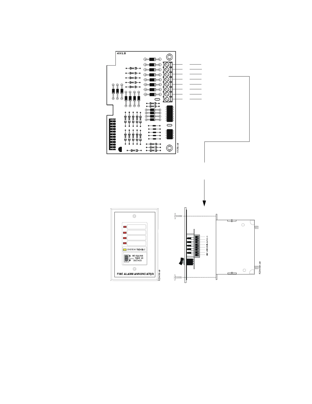
Figure 12 LED Interface Module - 4XLM
Connect to corresponding terminals
of RZA-4X Remote Annunciator.
Note: Make wiring connections with system
power off. Maximum wire impedance is 50
ohms per wiring connection.
Front View
Side View
Single-gang Box
1 +24V
2 Out#1
3 Out#2
4 Out#3
5 Out#4
6 System Trouble
7 Sound
8 Resound


#

Table of Contents

Questions and Answers:

Question and Answer IconNeed help?

Do you have a question about the System Sensor PDRP-1001 and is the answer not in the manual?

System Sensor PDRP-1001 Specifications

General IconGeneral
BrandSystem Sensor
ModelPDRP-1001
CategoryControl Panel
LanguageEnglish

Related product manuals