Transmitter Module - 4XTM (NOTIFIER)
3 Installation Procedure
The PDRP-1001 PN 50734:C 03/11/99 23
Transmitter Module - 4XTM (NOTIFIER)
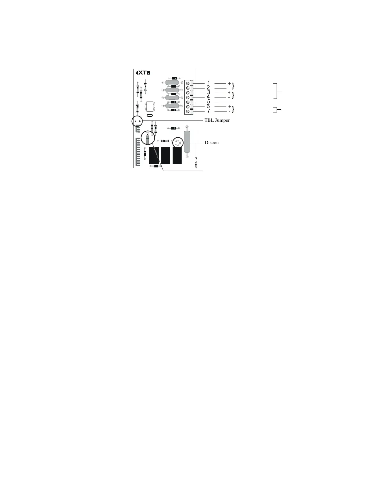
Polarities shown in activated positions. The wiring of this module must follow the
requirements as specified in the “General” section, “
UL Power Limited Wiring
Requirements.
”
Push the disconnect switch down to prevent unwanted activation of the Municipal Box
and Remote Station Outputs during testing of the control panel. The Disconnect LED
will remain illuminated while the Municipal Box is disconnected. The System Trouble
LED will indicate disconnected and/or Open Circuit conditions on the Municipal box.
Cutting the TBL jumper will allow the alarm reverse polarity circuit to open on trouble,
if no alarm exists
.
Note: Remote Alarm, Remote Trouble, and Municipal Box wiring can leave the building.
TBL Jumper
Disconnect LED
Disconnect Switch
Remote Alarm
Remote Trouble
No Connection
Municipal Box*
* Dummy load terminals
6 and 7 (4.7K, 1/4 W
resistor) if Municipal
Box is not connected.
Power Limited Circuit
Non-Power Limited Circuit
#