Front Panel Control Switches
1 The PDRP-1001/PDRP-1001A/PDRP-1001E
The PDRP-1001 PN 50734:C 03/11/99 7
Front Panel Control Switches
Switch 1 Tone Silence
Switch 2 Alarm Silence
Switch 3 Alarm Activate
Switch 4 System Reset
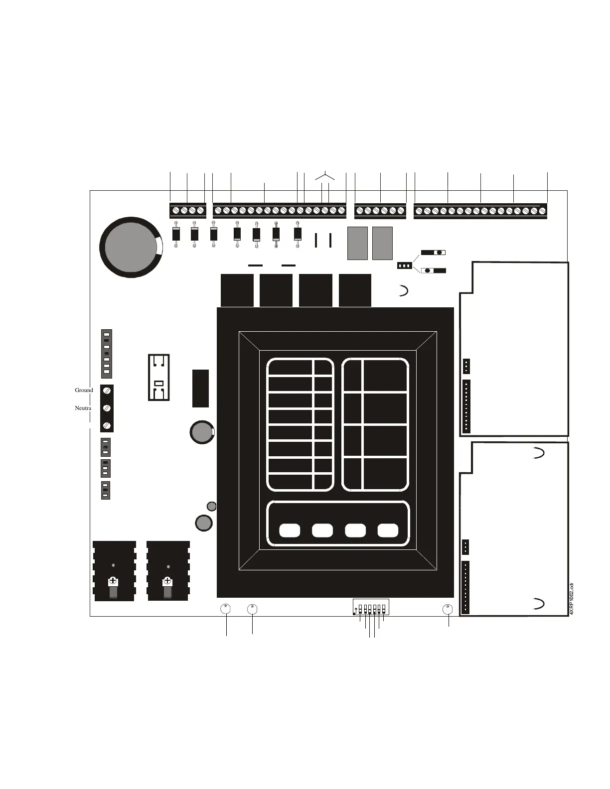
Figure 1 PDRP-1001/PDRP-1001A/PDRP-1001E Installation Diagram
B+ A+ A- B-B+ A+ A- B-
B+ A+ A- B-
B+ A+ A- B-
TB1
TB2
TB3
TB4
BATT
EARTH
JP 1
SUPV 2
GEN ALM2
J1
J2
J9
J3
NO DACT
DACT
SW1
123456
O
N
-
+
NO NC C NO NC C
B+ B-
B+ B-
B+ A+ A- B-
B+ A+ A- B-
+ -
+ -
+24VNR
+24VR
TB5
+24VU
*
*
+ -
24 VVU
RMS-REGULATED
24 VR
REGULATED
RESETTABLE
24 VNR
REGULATED
NON-RESETTABLE
1234
Notification Appliance
Circuits
Class A (Style Z)
Class B (Style Y)
Releasing
Circuits
Relays
TroubleAlarm
Contacts Contacts
1234
Initiating Device Circuits
Class A (Style D)/Class B (Style B)
Manual
Release
4XTM
or
4XLM
or
4XZM
4XTM
or
4XLM
or
4XZM
*Option Board Jumpers
are underneath lower
module.
OPT 1
OPT 2
Micro Fail LED
Not Used
Discharge Timer
Discharge Timer
Cross-Zone
Dual Hazard
Discharge Timer
Ground Fault LEDBattery Fail LED
Batteries
Optional Ammeter
Connection
Transformer
AC Circuit Breaker
Optional Voltmeter
Connection
Ground
Neutral
Hot