Voltmeter/Ammeter
3 Installation Procedure
The PDRP-1001 PN 50734:C 03/11/99 21
Optional Modules
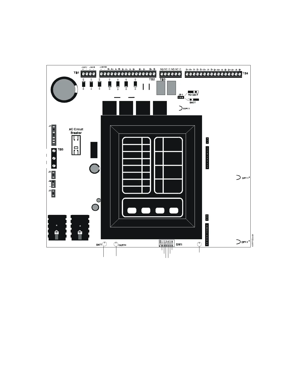
The fire control panel has two module connectors - J5 and J8. Three modules are
available for the panel and they can be used in any combination, including duplicate
modules. The corresponding option jumper must be cut before installation of an
optional module, to enable module supervision.
Figure 10 Optional Panel Modules
Note:
• Optional 4XLM module for an RZA-4X Annunciator must be installed on J7 and J8
only
.
• 4XTM and 4XZM modules can be installed in either location.
*Jumper “OPT 2”
must be cut if a
module is
installed in this
position
Micro Fail LED
Not Used
Discharge Timer
Discharge Timer
Cross Zone
Dual Hazard
Discharge Timer
Ground Fault LEDBattery Fail LED
*Jumper “OPT 1”
must be cut if a
module is
installed in this
position
Batteries
Optional Ammeter
Connection
Transformer
Optional
VoltmeterConnection
Hot
Neutral
Ground
#