EasyManuals Logo

System Sensor PDRP-1001 User Manual

System Sensor PDRP-1001
44 pages
To Next Page IconTo Next Page
To Previous Page IconTo Previous Page
Page #26 background imageLoading...
Page #26 background image
3 Installation Procedure
LED Interface Module - 4XLM (NOTIFIER)
26 The PDRP-1001 PN 50734:C 03/11/99
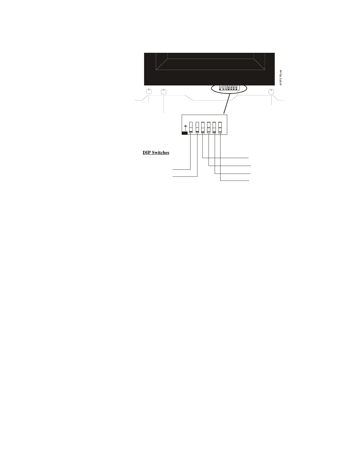
Dip Switch Location and Descriptions
For DIP switch settings, refer to the Section “
Setting Mode of Operation
.”
Note: The Reset key must be depressed after any switch configuration has been made.
1
2
34
5
6
O
N
1
2
3456
O
N
Battery Fail LED
Ground Fault LED
Micro Fail LED
Switch 3: DISCHARGE TIMER
Switch 4: DISCHARGE TIMER
Switch 5: DISCHARGE TIMER
Switch 6: NOT USED
Switch 1: CROSS ZONE
Switch 2: DUAL HAZARD
$
DIP Switches

Table of Contents

Questions and Answers:

Question and Answer IconNeed help?

Do you have a question about the System Sensor PDRP-1001 and is the answer not in the manual?

System Sensor PDRP-1001 Specifications

General IconGeneral
BrandSystem Sensor
ModelPDRP-1001
CategoryControl Panel
LanguageEnglish

Related product manuals