3 Installation Procedure
Notification Appliance Circuits
18 The PDRP-1001 PN 50734:C 03/11/99
Output Circuits
Notification Appliance Circuits
This control panel can provide two Class A (Style Z)/Class B (Style Y) Notification
Appliance Circuits and two Class B (Style Y) Releasing Circuits (see section “Setting
Mode of Operation” for DIP switch configuration). Each circuit is capable of 1.5 amps
of current. Total current drawn from all four circuits cannot exceed 2.25 amps. Refer
to the Compatibility Chart. Circuits are supervised and power-limited.
Note: Wiring must be configured to maintain a minimum voltage of 20.4V on release circuits. Calculation of
maximum allowable resistance:
R
MAX
= 20.6V-20.4V
________________________________________________________________________
I
S
Where:
R
MAX
= maximum allowable resistance of wiring
I
S
= solenoid current
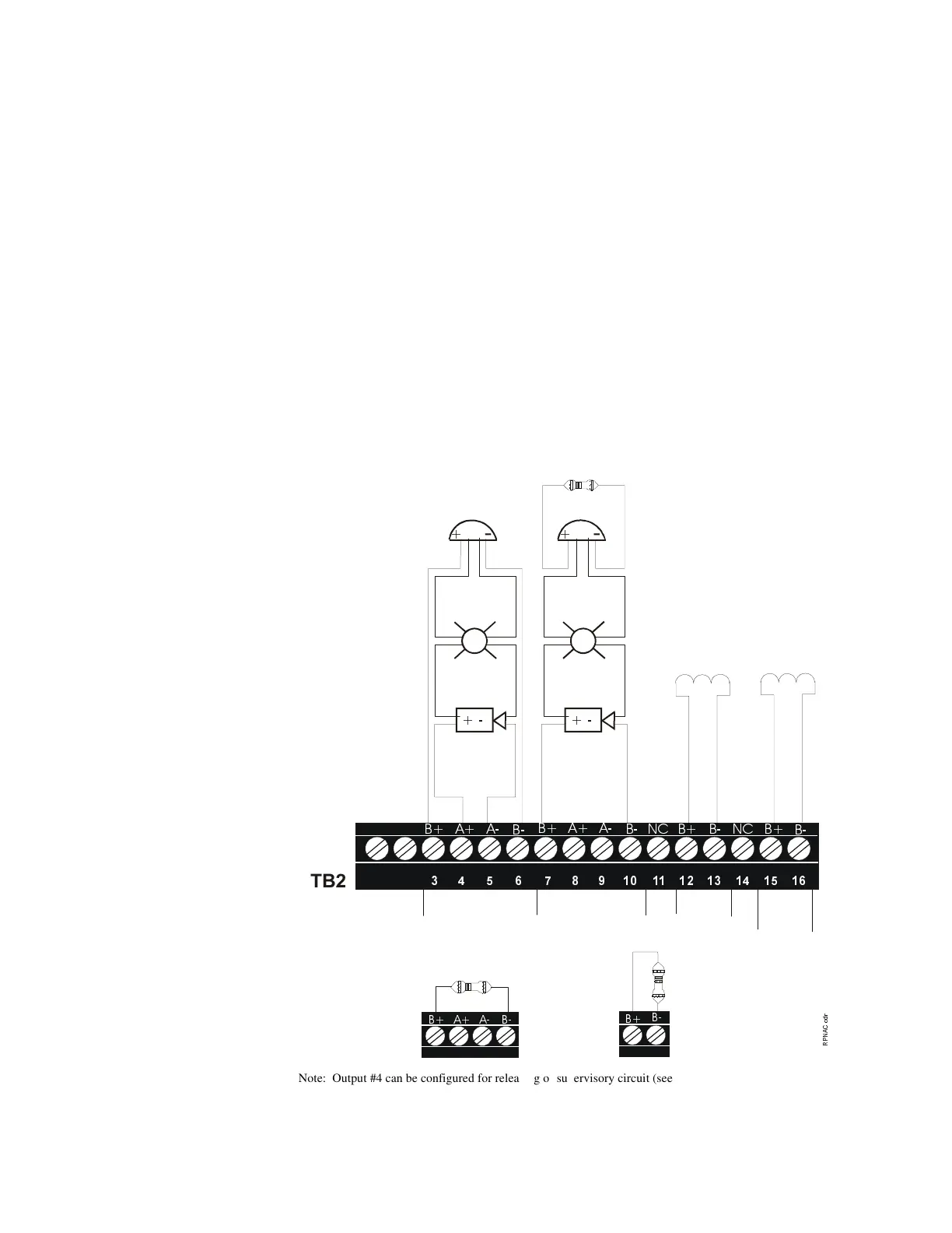
Figure 6 Notification Appliance Circuits
!
Note: Output #4 can be configured for releasing or supervisory circuit (see Section “Setting Mode of Operation”). If
configured as a releasing circuit, the circuit will be non-power limited. If configured as a supervisory circuit, the circuit
will be power limited. All wiring must follow the power limited “General” Section.
Dummy Load all
unused Notification
Appliance Circuits
Dummy Load all
unused Releasing
Circuits
4.7K, 1/4-Watt
UL-Listed End-of-Line device
4.7K, 1/4-Watt
OUT #1
OUT #2
OUT #3
OUT #4
See note
below
Polarized Horn
Polarized Strobe
Polarized Bell
Class A
(Style Z)
Notification
Appliance Circuit
Class B (Style Y) Notification
Appliance Circuit
4.7K, 1/2-Watt
(NOTIFIER part #71252 UL listed)
Releasing Circuits
UL listed & FM approved
Releasing Devices, refer to
Appendix B: Device
Compatibility.
No Connection
No Connection