NFPA 72 Signaling Systems for Central Station Service
Appendix C: NFPA Standard-Specific Requirements
The PDRP-1001 PN 50734:C 03/11/99 37
NFPA 72 Signaling Systems for Central Station Service
(Protected Premises Unit) and Remote Station Fire Alarm System (Protected Premises Unit)
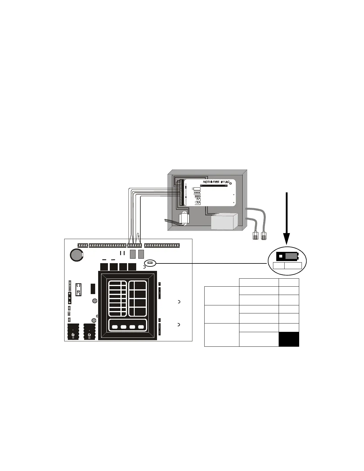
NOTI•FIRE 911AC DACT* - for connection to a Central Station Receiver or Protected
Premises Receiving Unit. This unit must be installed as illustrated below. For
additional information on the 911AC, refer to document 74-06200-005.
All connections between the FACP and 911AC must be in conduit, less than 20 ft
(609.6cm) in length in the same room. If the NOTI•FIRE 911AC is not mounted in the
PDRP-1001/PDRP-1001A/PDRP-1001E backbox all connections must be in conduit,
less than 20 ft. (609.6 cm) in length in the same room.
*This application using the NOTI•FIRE 911AC is not FM approved.
Note: For 911AC
• The Maximum standby load shall be 125 mA.
• The Standby by Battery Requirement: 24VDC, 7Amp-Hour-Max.
• The PDRP-1001/PDRP-1001A/PDRP-1001E is not suitable for transmission of a supervisory signal to
the DACT.
Figure 13 NFPA 72 Signaling Systems for Central Station Service
1
2
4
6
7
8
9
10
11
12
3
5
1
2
5
6
7
8
9
10
12
13
14
15
16
17
3
4
11
12VAC, 20VA, 60Hz or +24VDC
12VAC, 20VA, 60Hz or -24VDC
(Refer to m anual)
BATTERY -
BATTERY +
INIT IATING A1 -
INIT IATING A2 -
INIT IATING B1 +
INIT IATING B2 +
S UPE RV IS OR Y H I
S UPE RV IS OR Y LO
TROUBLE RELAY NC
TROUBLE RELAY COM
TROUBLE RELAY NO
ALARM RELAY NC
ALARM RELAY COM
ALARM RELAY NO
Digital Alarm Communicator Transmitter Listed for Ce ntral Station or Remote Station Service.
Slide Cover Back to Access Programm ing Ja ck an d Relays
Primary RJ31X
Tel co Jac k
Altern ate RJ31X
Tel co Jac k
- 12 VDC Sealed
Rechargeable
+ Batt ery
PS1270
12Volt
7AH Battery
+
-
NOTE on STD DACT:
Place jumper over pins 2 and 3,
marked DACT, when employing a
DACT. This directs the control panel
to transmit all trouble conditions
except AC LOSS.
STDDACT
To Central Station
Alarm
JP-1
Motherboard 911AC
Alarm
normally open
contacts
TB3-1 6 and 7
TB3-3 8 and 9
Trouble
normally open
contacts
TB3-4 10
TB3-6 11
Supervisory
normally open
contacts
4XZM TB1-12 12
jumper TB3-6 to
4XZM TB1-10
Note: The PDRP-1001/
PDRP-1001A/PDRP-
1001E is not suitable for
transmission of a
supervisory signal to the
DACT
RP911AC.CD
To AC
Power