9—22
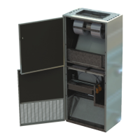
1‐4mm
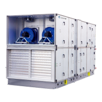
Fig.7and8
Sensorforcontrolofrotationmustbe
installedbytheinstaller.Distance
mustbe1‐4mmbetweensensorand
rotor.Checkthatthebracketswhich
areusedfortheassemblyoftherotor
segmentsdonothitthesensor.
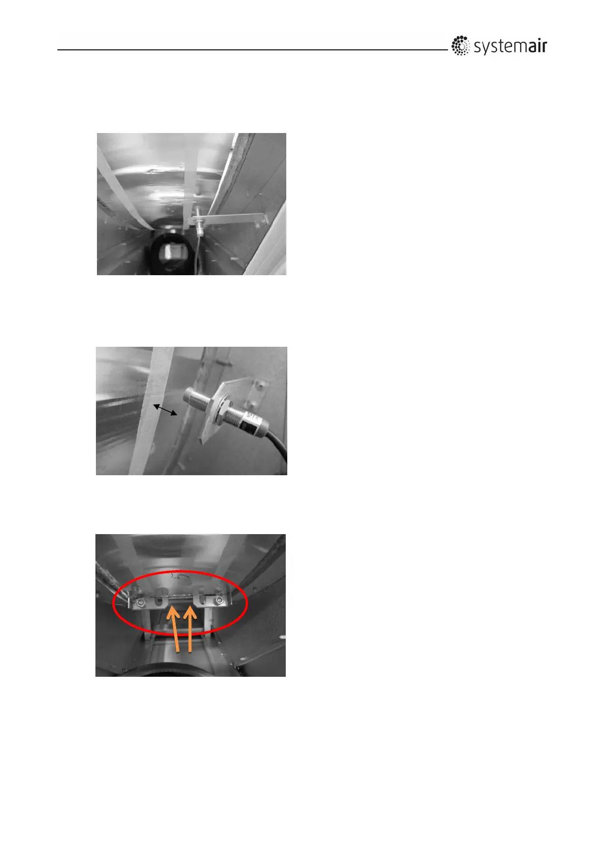
Fig.9
Payattentiontotheheightsofthe
bracketswhichareusedforthe
assemblyoftherotorsegments.
Pleaseturntherotorbyhandinorder
toverifythatthesens orwillnotbe
hitbythebrackets.
Fig.8
Fig.9
Fig.7