ARES-G2 Getting Started Guide Page 47
OSP Panel Signal Connections
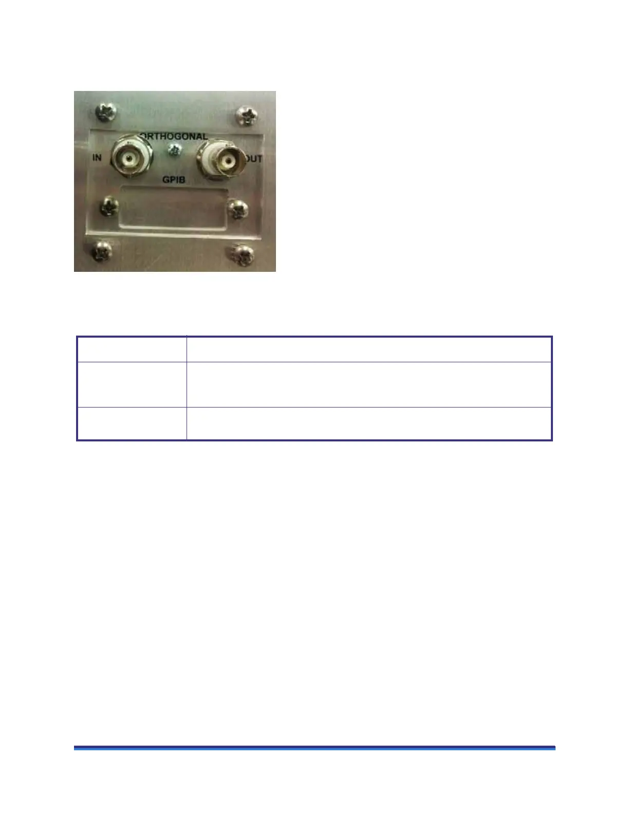
The figure below identifies the connections on the OSP/GPIB signal panel.
Figure 26 ARES-G2 lower signal panel
The table below contains information regarding the set of connectors at the OSP/GPIB signal panel..
Connector Purpose
ORTHOGONAL IN CMD displacement signal for axial displacement, defined using TRIOS software in
Orthogonal Superposition mode (OSP). Scaling is ± 5.0 VDC = ± 50 micron displace-
ment.
ORTHOGONAL OUT Outputs a DC voltage proportional to the axial transducer displacement in Orthogonal
Superposition mode (OSP). Scaling is ± 5.0 VDC = ± 50 micron displacement.