ARES-G2 Getting Started Guide Page 46
Lower Panel Signal Connections
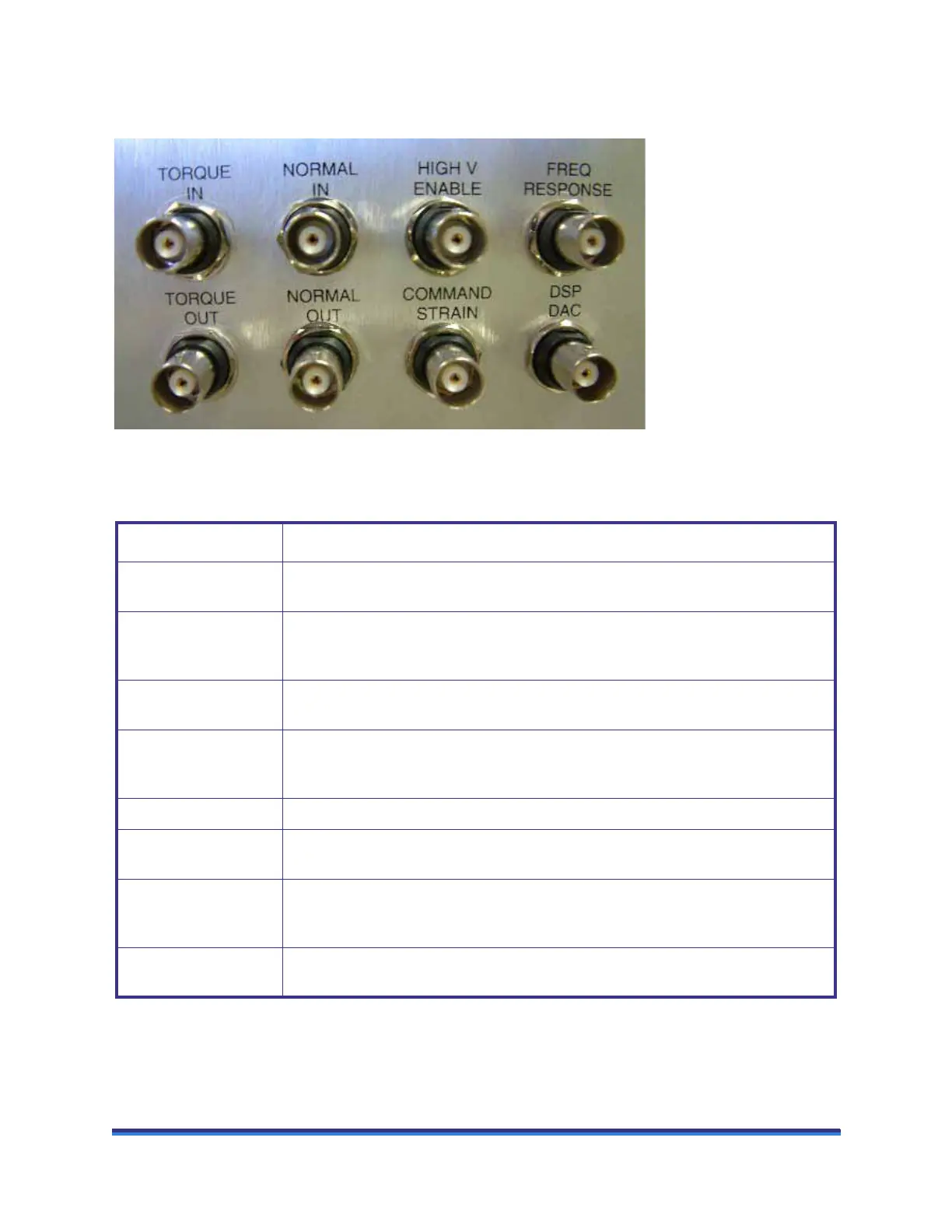
The figure below identifies the upper set of connections on the signal panel
Figure 25 ARES-G2 lower signal panel.
The table below contains information regarding the lower set of signal panel connectors.
Connector Purpose
TORQUE IN An external user input that can be connected to the internal torque measurement chan-
nel instead of the transducer torque signal. (User selectable.)
TORQUE OUT Outputs a DC voltage that is proportional to transducer torque.
Scaling is ± 5.0 VDC = ± Full Scale Torque
NORMAL IN An external user input that can be connected to the internal normal force measurement
channel instead of the transducer normal force signal. (User selectable.)
NORMAL OUT Outputs a DC voltage that is proportional to the transducer normal force.
Scaling is ± 5.0 VDC = ± Full Scale Normal
COMMAND STRAIN Outputs a DC voltage that is proportional to the actual motor defection.
HIGH V ENABLE A relay contact closure that is used to enable the High Voltage amplifier of the ER
option.
FREQ RESPONSE An input signal, defined using the TRIOS software, that can be sampled simultane-
ously with the Transducer Torque and Normal Force signals during an experiment.
Input scaling is ± 5 VDC.
DSP DAC A general purpose ± 10-volt analog output for future use that is derived from a digital-
to-analog converter on the DSP board.