ARES-G2 Getting Started Guide Page 45
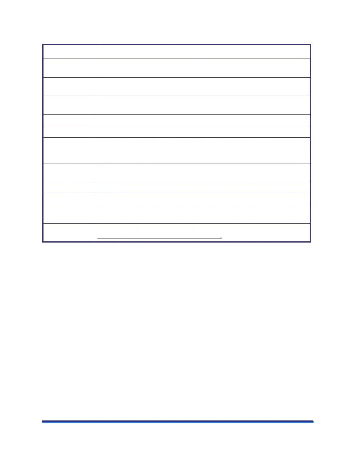
The table below contains information regarding the upper set of signal panel connectors.
Connector Purpose
VIDEO OUT Outputs the video signal from the ARES-G2 camera option to the controller computer for
display.
ANALOG 1 IN Accepts a ±10 VDC signal that can be sampled and stored in the experiment data file. This
input is defined through the TRIOS program.
ANALOG 2 IN Accepts a ±10 VDC signal that can be sampled and stored in the experiment data file. This
input signal is defined using the TRIOS program.
ANALOG 1 OUT A ±10 VDC signal that is defined using the TRIOS program.
ANALOG 2 OUT A ±10 VDC signal that is defined using the TRIOS program.
CAMERA Connection for the cable between the ARES-G2 test station and the camera located inside
the Forced Convection Oven. (This includes power, camera control signals, and camera
output.)
COM 1 A serial port output from the system CPU. This port will be used for communication to an
external circulator.
COM 2 A serial port output from the CPU. (For future use.)
OVEN CAN bus connection to the Forced Convection Oven option.
DIGITAL I/O TTL-compatible input and output signals and relay contact closures. They are defined
using the TRIOS software.
NETWORK Connection for communication between the ARES-G2 and the system network. (See
“Connecting the Computer to the Switch” on page 54
.)