Tandy
1000
Technical
Reference
Manual
BUS INTERFACE SPECIFICATIONS
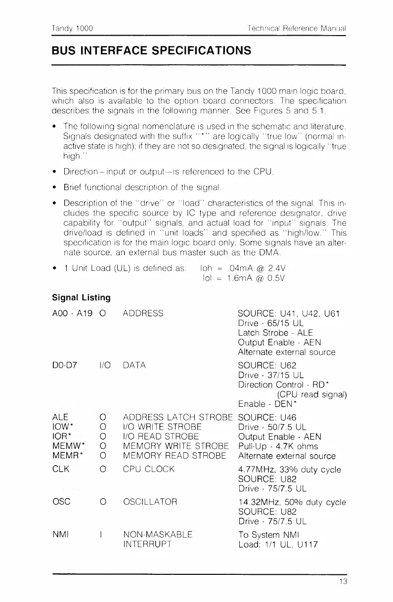
This specification IS for the primary bus on the
Tandy
1000
main logic board,
which also
is
available to the option board connectors. The specification
describes the signals
in
the following manner. See Figures 5 and 5.1.
• The following signal nomenclature IS used
In
the schematic and literature.
Signals designated with the
suffix"
*"
are
logically;
'true low" (normal in-
active state
is
high);
if
they are not so designated, the signal
is
logically'
'true
high,"
• Dlrection-- input or
output-is
referenced to the CPU.
• Brief functional description of the signal,
• Description of the
"drive"
or
"load"
characteristics of the signal This
in-
cludes the specific source
by
IC
type
and reference designator, drive
capability for
"output"
signals, and actual load for "input" signals The
drive/load
is
defined
in
"unit
loads"
and speCified as
"high/low."
This
speCification
is
for the main logiC board only. Some signals have an alter-
nate source, an external bus master such as the
DMA.
• 1 Unit Load (UL)
is
defined as loh
,04mA
@ 2.4V
101
=
1,6mA
@ 0,5V
Signal Listing
AOO
-
A19
0 ADDRESS
00-07
ALE
10W*
IOR*
MEMW*
MEMR*
CLK
OSC
NMI
SOURCE: U41, U42, U61
Drive - 65/15
UL
Latch Strobe - ALE
Output
Enable - AEN
Alternate external
source
I/O DATA SOURCE: U62
Drive -
37/15
UL
Di
rection Control - R0 *
(CPU read signal)
Enable - DEN *
o ADDRESS LATCH STROBE SOURCE:
U46
o I/O WRITE STROBE Drive - 50/7,5
UL
o I/O READ STROBE
Output
Enable - AEN
o
MEMORY
WRITE STROBE Pull-Up - 4.7K ohms
o
MEMORY
READ STROBE Alternate external source
o CPU
CLOCK
4.77MHz,
33%
duty
cycle
SOURCE:
U82
Drive - 75/7.5
UL
o OSCILLATOR
14.32MHz,
50%
duty cycle
SOURCE: U82
Drive - 75/7.5
UL
NON-MASKABLE
To System NMI
INTERRUPT Load:
1/1
UL, U117
13
 Loading...


