Tandy 1000
Technical Reference Manual
Palette Registers
The palette
is
a 16 x 4 high speed RAM that lets you redefine any color.
To
load the palette, write the hex address to the video array address register at
3DA. (The 16 palette registers are located at addresses 10
-1
F.)
Then the new
palette color
is
written to 3DE. Only the 4 least significant bits are used
as
shown
by the following table:
Bit
Description
o Blue
1 Green
2 Red
3 Intensity
Palette Register Format
Bit 4 of the video array address register
is
used to select the palette. Once
the palette
is
selected, hashing or noise will be observed on the display. To
avoid this effect, the palette should be accessed during vertical or horizontal
blanking, and the address register should be
changed
to less than 10 prior
to returning to normal operation.
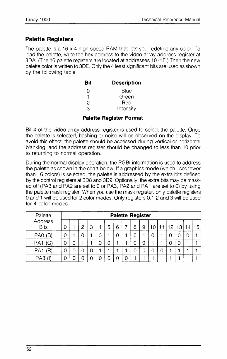
During the normal display operation, the RGBI information
is
used to address
the palette
as
shown
in
the chart below.
If
a graphics
mode
(which uses fewer
than 16 colors)
is
selected, the palette
is
addressed
by
the extra bits defined
by the control registers
at
308
and 309. Optionally, the extra bits may
be
mask-
ed off (PA3 and PA2 are set to 0 or PA3, PA2 and PA 1 are set to
0)
by using
the palette mask register. When you
use
the mask register, only palette registers
oand 1 will be used for 2 color modes. Only registers 0,1,2 and 3 will be used
for 4 color modes.
Palette
Palette Register
Address
Bits
0
1
2 3 4
5 6
7 8 9 10
11
12 13
14 15
PAO
(B)
0 1
0
1
0
1
0
1 0 1
0
1
0 0 0
1
PA1
(G)
0 0 1
1
0 0
1 1 0 0 1 1
0 0 1
1
PA1
(R)
0 0 0 0
1 1 1 1
0 0 0 0
1
1 1 1
PA3
(I)
0
0 0 0 0 0 0 0
1 1 1 1 1
1 1
1
52
 Loading...


