Tandy 1000
8255A18255A·5
Technical Reference Manual
(RESET)
Re
..
t. A
"high"
on this Input clears the control register
and all porta (A,
e,
C) are set
to
the input mode.
Group A and Group B
Control.
The
functional
configuration
of
each port Is program·
med
b)
the
Iystems
software. In essence, the CPU
"out·
puts"
a
control
word
to
the 8255A. The
control
word con·
talnslnformatlon
luch
as
"mode",
"bit
set",
"bit
reset",
etc.,
~hat
Initializes
the
functional
configuration
of the
8255A.
Each
of
the
Control blocks (Group A and
Group
8)
accepts
"com:nands"
from the ReadlWrite Control Logic. receives
"control
words"
from
the
internal data bus and issues
the
proper
commands
to its dssociated ports.
Control
Group
A - Port A and Port C
upper
(C7·C4)
Control
Group
8 -
Port
8 and Port
Clower
(C3·COI
The
Control
Word Register can
~
be
wrillen
into. No
Read
operation
of
the
Control Word Register
is
allowed.
Ports A. B. and C
The 8255A
contains
three B·bit
ports
(A,
B,
and
C).
All
can be
configured
In a wide variety
of
functional charac·
terlstlcs
by
the
system
software
but
each has
its
own
special features or
"personality"
to
further enhance
the
power and
flexibility
of
the 8255A.
Port
A.
One B·blt
data
output
latch/buffer
and one B·bit
data
input
latch.
Port
B.
One
8·bit
data
inpul/output
latch/buffer and one
8·bit
data
input
buffer.
Port
C.
One B·bit
data
output
latch/buffer
and one B·bit
data
input
buffer
(no
latch
for
Input). This port can be
divided
into
two
4·blt
ports
under the mode
control.
Each
4·bit
port
contains
a
4·bit
latch
and It can be used
for
the
control
signal
outputs
and
status
signal
inputs
in
conjunction
with
ports
A and
B:
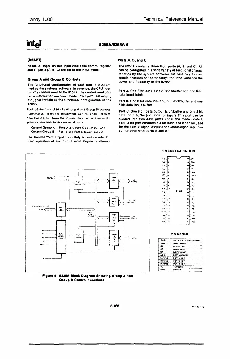
PIN CONFIGURATION
poe
..
pcaC·
"
1255A
'"
-'0.
"C~
:-
"
"
0,
n
:0,
"
0,
1'(1':
"
"
Vee
"0
~
"
"
....
"II'
~
"
"
,,,,
'.'
>0
PIN NAMES
Flgur.
4.
.225A
Block
DIagram Showing Group A and
Group
It
Control
Function.
6-168
 Loading...


