Tandy 1000
Technical Reference Manual
8272A
NO
stands
for
operation
in
the
Non·DMA
Mode
Skip
New
Cylinder
Number
NCN
stands
lor
a
new
Cylinder
number,
which
is
going
10
De
reached
as
a
result
~'e~~e
Seek
operation,
Desired
position
01
sc
f----
f--~~----
NO
Non-DMA
Mode
into
the
Data Register. The DIO (DB6) and ROM (DB7)
bits
in
the
Main
Status
Register
must
be in
the
"0"
and
"1"
states
respectively,
before
each
byte
of
the
com-
mand
may
be
written
into
the 8272A. The
beginning
of
the
execution
phase
for any
of
these
commands
will
cause
DIO and ROM
to
switch
to
"1"
and
"0"
states
respecti
ve
Iy
READ
DATA
A set
of
nine
(9)
byte
words
are required
to
place
the
FDC
into
the Read Data Mode.
After
the Read Data com-
mand has been
issued
the FDC
loads
the head (if it is in
the unloaded state),
waits
the
specified
head
settling
time
(defined
in
the
Specify
Command), and begins
reading ID
Address
Marks and
10
fields. When the cur-
rent
sector
number
("R")
stored
in the
ID
Register
(lOR)
compares
with
the
sector
number
read
off
the
diskette,
then the FDC
outputs
data
(from
the
data field) byte-by-
byte
to
the
m_ain
system
via the
data
bus.
After
completion
of
the read
operation
from the
current
sector, the
Sector
Number
is
incremented
by one, and
the
data
from
the
next
sector
is read and
output
on
the
data
bus. This
continuous
read
function
is
called
a
"Multi-Sector
Read
Operation."
The Read Data Com-
mand
must
be
terminated
by the receipt
of
a Terminal
Count
signal.
Upon
receipt
of
this
signal, the FDC
stops
outputting
data
to
the
processor,
but
will
continlje
to
read
data
from
the
current
sector,
check
CRC (Cyclic
Redundancy Count) bytes, and then at the end
of
the
sector
terminate
the
Read Data
Command.
The
amount
of
data
which
can be handled
with
a
single
command
to
the FDC
depends
upon
MT
(multi-track),
MFM
(MFM/FM),
and
N
(Number
of
ByteS/Sector). Table
7
on
the
next
page
shows
the
Transfer
Capacity.
~--+.,------c-_.--
PeN
Presenl
Cylinder
Number
~~~~~-~--~
--
---
--~~
-----
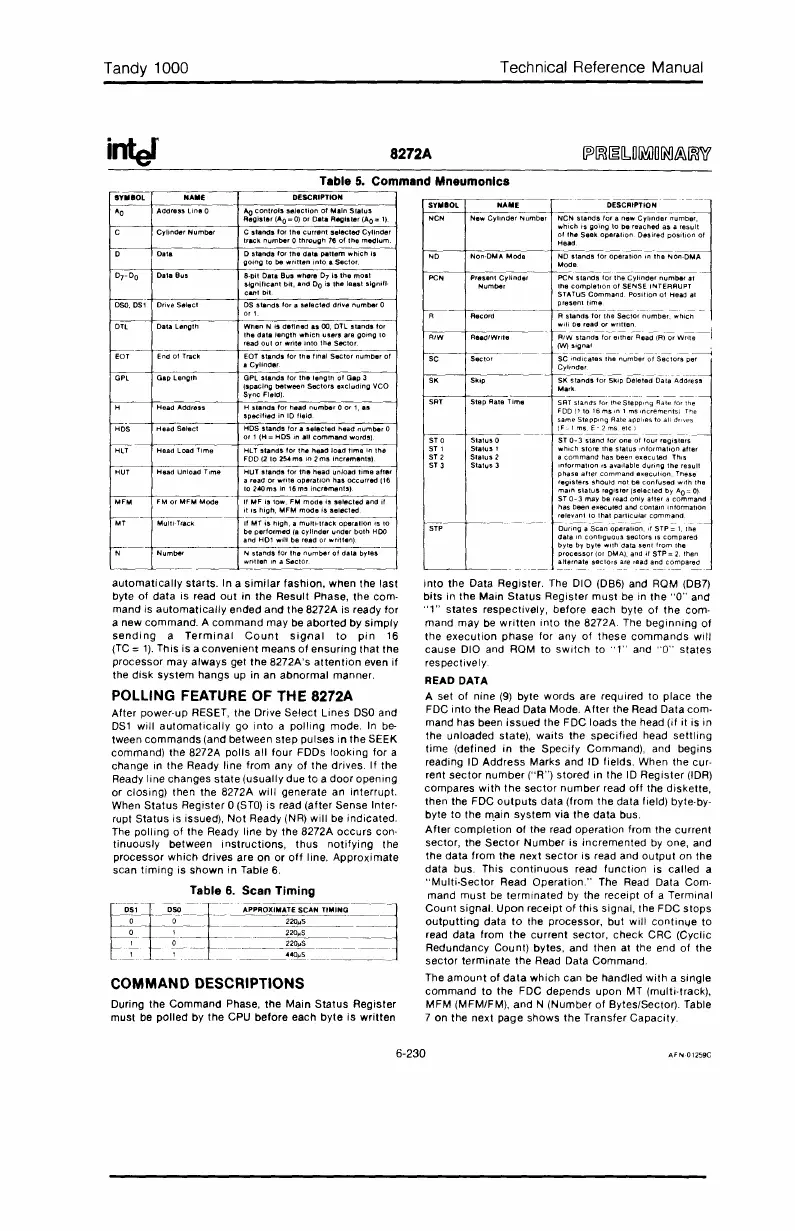
SYMBOL NAME DESCRIPTION
PeN
SIands
tor
the
Cylinder
number
at
the
completion
01
SENSE INTERRUPT
STATUS
Command,
Position
01
Head at
~----J-------------
~~n~~
_
R
stands
lor
the
Sector
number,
which
~---J--R'-'d-'W-'-ite---
.j-~:;~b:t~~:~~;~:~:~R~ad(Rl~
wm;--j
~-~~---
-----
--------4
SC
indicates
the
number
01
Sectors
per
Cylinder
f--~
-~
----------.
SK
stands
for
Skip
Deleted
Data
Address
Mark
f----+---:.,------'----~------~-
- -
-~
Step
Aale
Time
SRT
stands
lor
the
StepPing
Rate tor the
FDD(1to16mSlOlms,ncrementsl
The
same
StepPing
Aateapol,esto
all drives
f--~-1---~.
_~
~~~2~_~~
.
__
._
ST 0
Status
0 ST
0-
3
stand
for
one
01
lour
registers
ST 1
Status
1
which
store
the
status
Information
after
ST 2
Slatus
2 a
command
has been
executed
ThiS
ST 3
Status
3
information
IS
available
during
the
result
phase
alter
command
execulion.
Ttlese
registers
stlould
not
be
con'used
with
ttle
main
status
reg1sler(selected
by
AO=O)
ST
0-
3
may
be read
only
alter
a
command
has
been
executed
and
contain
information
relevant
10
that
particular
command
f-
.
--
,--
-
~.
--.
- -
During
a
Scan
operation,
if
STP=
1,
the
data
In
contiguous
sectors
IS
compared
byte
by
byle
.....
ilhdatasent
lromthe
processor
(or DMA), and
if
STP =
2,
then
alternate
sectors
are read and
compared
---
----
--
--
---
--
DESCRIPTION
8-DII
Data
Bus
where
07
is
the
moat
~~~i~~tnt
bit,
and
DO
is
the
least
slgnill·
C
,lands
for
the
current
se1ecte<J
Cylinder
track
number
0
througtl
76
of
the
me<Jlum
o
stands
lor
the
dala
pattem
which
is
going
10
be
written
into
a
Sector
Wtlen
N Is
defined
.5
00,
DTl
stands
for
thedst.'ength
whictl
users
are gOing
10
read
oul
or
write
inlo
the
Seclor
OS
stands
lor
a
selected
drlye
number
0
m1
EDT
stands
for
lrltllinal
Sector
numDerol
a CyUnder
GPl
stands
ror
the
lenglt!
01
Gap
3
(spacIng
between
Sector,
excluding
veo
Sync
Field)
Ao
controls
selection
or
Main
Slatus
Register
(A
O
=
0)
or
Oala Regiater (AO=
1)
Data
lengltl
Gap
length
Table
5.
Command Mneumonlcs
cc=~r---c-=-c---.-----cc=-ccc==cc--~
DTL
COMMAND DESCRIPTIONS
H
slands
for
tlead
number
0
or
1,
as
specified
in
10
field
~DS·~-+-H:-"-:d·;;-S.-:'.-:c'---+C-H""DS;;-.:"-'.-nd:-'-;-'o-,,-,,-:',-:c'-.d-:h-
••
-:d
n-u-:mbe-,-:o--1
or
1 (H =
HDS
in
all
command
words)
r;m-
-t-cH-:"-:d-:loa-d-:TC-im-.--+-H-:L
TO:-,-:,.-oo-:,
"--,o,-:,"-:.-:h.-.d-:'-o.-:d
'-:im-.
-:in-:'h-.
-l
FDD
(2
10
25..
ms
in
2
ms
increments)
During the
Command
Phase,
the
Main
Status
Register
must be
polled
by
the
CPU
before
each
byte
is
written
POLLING FEATURE OF THE 8272A
After power-up RESET,
the
Drive
Select
Lines
DSO
and
DS1
will
automatically
go
into
a
polling
mode.
In
be-
tween
commands
(and
between
step
pulses
in
the SEEK
command) the 8272A
polls
all
four
FDDs
looking
for
a
change in
the
Ready line
from
any
of
the
drives.
If
the
Ready line changes
state
(usually
due to a
door
opening
or
closing)
then the 8272A
will
generate an
interrupt.
When
Status
Register
0
(STO)
is read
(after
Sense Inter-
rupt
Status
is issued),
Not
Ready (NR)
will
be
indicated.
The
polling
of
the Ready line by the 8272A
occurs
con-
tinuously
between
instructions,
thus
notifying
the
processor
which
drives are
on
or
off
line.
Approximate
scan
timing
is
shown
in
Table
6.
SY
..
BOL
N
....
E
"0
Addrus
Line
0
Cylinder
Number
Dala
DrDO
Dala Bus
~;
Driye Select
Head
Unload
Time
HUT
stands
for
ttle
head
unload
lime
after
a read
or
write
operation
has
occurred
(16
lo2AOmsin
16msincremenlS)
~M--+':-M-O-:'
"'-:'-"'-:"'-00-.
-
+-If-"'-:'
-i.
-'ow-.-:'
...
-m-o-d'-i'-'-"'-C-"d-.-nd-it----1
it
is
high,
MFM
mOde
is
selecled
f-----
---~~-
MT
Multi-Track
If
MT
is
tligh,
a
multi-track
operation
is
10
be
performed
(a
cylinder
under
both
HDO
and
HD1
wltl
be read
orwriltenj
r-,;--
'-~-to"henUmbe,otd"'bY'"
written
in a
Sector
_~_
~_~
__
--'-
-J
automatically
starts.
In a
similar
fashion,
when the last
byte
of
data
is read
out
in
the
Result Phase, the com-
mand is
automatically
ended
and
the
8272A is ready
for
a
new
command.
A
command
may
be
aborted
by
simply
sending
a
Terminal
Count
signal
to
pin
16
(TC
=
1).
This is a
convenient
means
of
ensuring
that
the
processor
may
always
get
the
8272A's
attention
even
if
the
disk
system
hangs
up in an
abnormal
manner.
6-230
 Loading...


