Tandy 1000
inter
8272A
Technical Reference Manual
During
the Command Phase
of
the Seek
operation
the
FDC is in the FDC BUSY state,
but
during
the
Execution
Phase
it
is in the NON BUSY state.
While
the
FDC is in
the NON BUSY state,
another
Seek Command may be
issued, and in
this
manner parallel seek operations may
be
done on up
to
4 Drives at once.
If
an FDD is in a NOT READY state at the beginning
of
the
command
execution phase
or
during
the seek opera·
tion, then the NR (NOT READY) flag is set in Status
Register 0 to a
1 (high), and the command is terminated.
Note
that
the 8272A Read and
Write
Commands
do
not
have
implird
Seeks. Any R/W
command
should be
preceded
by:
1)
Seek Command;
2)
Sense Interrupt
Status; and
3)
Read ID.
RECALIBRATE
This command causes the read/write head
within
the
FDD
to
retract
to
the Track 0 position. The FDC clears
the
contents
of
the PCN counter, and
checks
the
status
of
the Track 0 signal from the FDD. As long as the Track
osignal is low, the Direction signal remains 1 (high) and
Step Pulses are issued. When the Track 0 signal goes
high, the SE (SEEK END) flag in
Status
Register 0 is set
to a 1 (high) and the
command
is terminated. If the Track
o signal is
still
low
after
77 Step Pulses have been
issued, the FDC sets the
SE
(SEEK END) and
EC
(EQUIP·
MENT CHECK) flags
of
Status
Register 0 to
both
1s
(highs), and terminates the command.
The
ability
to
overlap RECALIBRATE Commands to
multiple
FDDs, and the loss
of
the READY signal,
as
described in the SEEK Command, also applies to the
RECALIBRATE Command.
SENSE INTERRUPT STATUS
An
Interrupt signal is generated by the FDC for one
of
the
following
reasons:
1.
Upon entering the Result Phase of:
a.
Read Data Command
b.
Read a Track Command
c.
Read
ID
Command
d.
Read Deleted Data Command
e.
Write Data Command
f.
Format a
Cylinder
Command
g.
Write
Deleted Data Command
h.
Scan Commands
2.
Ready Line
of
FDD changes state
3.
End
of
Seek or Recalibrate Command
4.
During Execution Phase in the NON·DMA Mode
Interrupts caused by reasons 1 and 4 above
occur
during
normal command operations and are easily
discernible
by
the
processor. However,
interrupts
caused
by
reasons 2 and 3 above may be
uniquely
identified
with
the aid
of
the Sense
Interrupt
Status
Command. This
command when issued resets the interrupt signal and
via
bits
5,
6,
and 7
of
Status
Register 0
identifies
the
cause
of
the interrupt.
Neither the Seek or Recalibrate Command have a Result
Phase. Therefore,
it
is
mandatory
to
use
the
Sense Inter-
rupt
Status
Command
after
these
commands
to
effec·
tively
terminate
them and
to
provide
verification
of
the
head
position
(PCN).
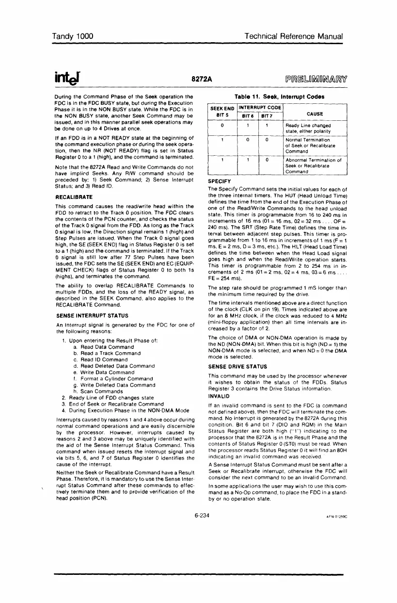
Table
11.
Seek, Interrupt Codes
SEEK END
INTERRUPT CODE
BIT 5
BIT6
BITT
CAUSE
0 1
1
Ready Line changed
state, either polarity
1 0 0 Normal Termination
of
Seek
or
Recalibrate
Command
1 1
0 Abnormal Termination
of
Seek or Recalibrale
Command
SPECIFY
The
Specify
Command
sets
the
initial
values for each
of
the
three
internal
timers. The HUT (Head Unload Time)
defines
the
time
from
the
end
of
the Execution Phase
of
one
of
the Read/Write
Commands
to the head unload
state. This
timer
is programmable from
16
to 240
ms
in
increments
of 16
ms
(01:
16 ms,
02:
32
ms.
"
OF:
240 ms). The SRT (Step Rate Time) defines the
time
in·
terval between adjacent
step
pulses. This
timer
is
pro·
grammable from 1
to
16
ms
in increments
of
1
ms
(F
: 1
ms,
E:
2 ms,
D:
3 ms, etc.). The
HlT
(Head
load
Time)
defines
the
time
between when the Head
load
signal
goes
high
and
when
the Read/Write operation starts.
This
timer
is programmable from 2 to
254
ms in in·
crements
of
2
ms
(01:
2 ms,
02:
4 ms,
03:
6
ms
.
FE:
254 ms).
The
step
rate
should
be
programmed 1 mS longer than
the
minimum
time
required
by
the drive.
The
time
intervals mentioned above are a direct
function
of
the
clock
(ClK
on pin 19). Times indicated above are
for
an
8 MHz
clock,
if
the
clock
was reduced
to
4 MHz
(mini·floppy
application)
then all time intervals are in·
creased by a
factor
of
2.
The
choice
of
DMA
or NON·DMA operation is made by
the ND (NON·DMA) bit. When
this
bit is high
(NO:
1)
the
NON·DMA mode
is
selected, and when
NO:
0 the DMA
mode is selected.
SENSE DRIVE STATUS
This
command
may be used by the processor whenever
it
wishes
to
obtain
the
status
of the FDDs. Status
Register 3
contains
the Drive Status information
INVALID
If
an
invalid
command
is sent to the FDC
(a
command
not
defined
above), then the FDC will terminate the com·
mand. No interrupt is generated
by
the 8272A during this
condition.
Bit
6
and
bit 7 (DIO and
ROM)
in the Main
Status
Register are both high ("1")
indicating
to the
processor
that
the 8272A is in the Result Phase and the
contents
of
Status
Register 0
(STO)
must
be
read. When
the
processor
reads
Status
Register 0
it
will find
an
80H
indicating
an
invalid command was received
A Sense Interrupt
Status
Command must be sent
after
a
Seek or Recalibrate interrupt, otherwise the FDC will
consider
the next
command
to
be
an
Invalid Command.
In some
applications
the user may wish to use
this
com·
mand
as
a No-Op command,
to
place the FDC in a stand·
by or no operation state.
6-234
 Loading...


