Tandy 1000
MC6845
CRTC DESCRIPTION
(Figure
8:
CRTC Block Diagram)
Technical Reference Manual
The CRTC consists of programmable horizontal and
vertical timing generators, programmable linear address
register, programmable cursor logic, light pen
capture
register, and control circuitry for interface
to
a processor
bus.
All CRTC timing
is
derived from
ClK,
usually the
output
of an external
dot
rate
counter.
Coincidence (CO)
circuits continuously
compare
counter
contents
to
the
contents
of the programmable register file, RO·R17. For
horizontal timing generation, comparisons result in:
1)
Horizontal sync pulse (HS) of a frequency, position, and
width
determined
by
the
registers. 2) Horizontal Display
Signal of a frequency. position, and
duration
determined
by
the
registers.
The Horizontal
counter
produces H clock which drives
the
Scan
line
Counter
and Vertical Control. The
contents
of
the
Raster
Counter
are continuously
compared
to
the
Max Scan
line
Address Register. A coincidence resets
the
Raster
Counter
and clocks
the
Vertical Counter.
Comparisons of Vertical
Counter
contents
and Vertical
Registers result in:
1)
Vertical sync pulse (VS)
of
a
frequency and positon
determined
by
the
registers-the
width
is
fixed
at
16 raster lines
in
the
vertical control
section and
is
not
programmable. 2) Vertical Display
of
a
frequency and position
determined
by
the
registers.
The Vertical
Control
logic
has
other
functions.
1.
Generate
row selects, RAO-RA4, from
the
Raster
Count
for the
corresponding
interlace or non-
interlace modes.
2.
Extend
the
number
of
scan lines
in
the
vertical
total
by
the
amount
programmed
in
the Vertical
Total Adjust Register.
The
linear
Address Generator
is
driven by
ClK
and locates the relative positions
of
characters
in
memory
with their positions on
the
screen. Fourteen lines,
MAO-MA13, are available for addressing up
to
four
pages of 4K characters, 8 pages
of
2K
characters, etc.
Using the
Start
Address Register. hardware scrolling
through 16K
characters
is
possible. The
linear
Address
Generator repeats the same sequence
of
addresses for each
scan line
of
a
character
row.
The cursor logic
determines
the
cursor location, size.
and blinking rate
on
the
screen_ All are programmable.
The light pen
strobe
going high causes the
current
contents
of
the
Address
Counter
to
be latched in
the
light
Pen Register.
The
contents
of
the
light
Pen Register
are subsequently read by
the
Processor.
Internal CRTC registers are programmed
by
the
processor through
the
data
bus.
00·07.
and
the
control
signals-RNi,
~,
RS
and
E.
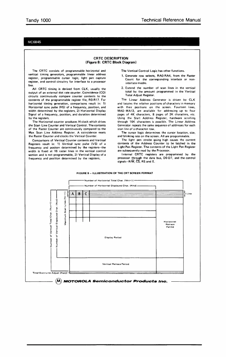
FIGURE 9 - ILLUSTRATION OF THE
CRT
SCREEN
FORMAT
r--Number
of
Horizontal
T~tal
Char.
(Nht+1)
I
r---
Number
01
Horizontal
Displayed
Char.
IN
hd)
------,
mm
A
W
B
C~~~~~~}Line
-
.:;
Horizontal
Retrace
Period
Display
Period
~t-----ve"-;C.'R"".cepe"O-d
--+------;
Total
Scan
Line
Adjust
(Nadil-l::==================3=====3
®
MOTOROLA
Semiconductor
Products
Inc.
 Loading...


