25
Model PH90 Operating Procedures
Section 6 Operating Procedures
Equipment Set Up
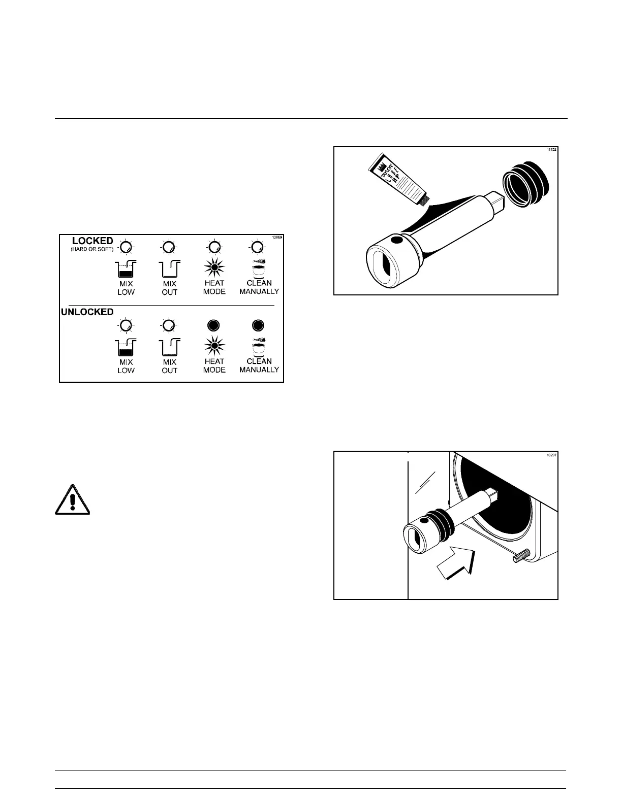
Evaluate the condition of lights and screen messages
(Hard Lock or Soft Lock, etc.) before performing
opening procedures. If all four LED’ s on the front of the
unit are lit, the unit is locked.
Figure 10
Freezing Cylinder Assembly -
Shake Side
MAKE SURE POWER SWITCH IS IN THE
“OFF ” POSITION. Failure to do so may cause injury
from hazardous moving parts, or electrocution.
Be certain your hands are sanitized before
assembling the freezer.
With the parts tray available for the shake side:
Step 1
Lubricate the groove and shaft portion that comes in
contact with the bearing on the beater drive shaft. Slide
the seal over the shaft and groove until it snaps into
place. DO NOT lubricate the square end of the drive
shaft. Fill the inside portion of the seal with 1/4” more
lubricant and evenly lubricate the end of the seal that
fits onto the rear shell bearing.
Note: When lubricating parts, use an approved food
grade lubricant (example: Taylor Lube HP).
Figure 11
Step 2
Install the drive shaft through the rear shell bearing in
the freezing cylinder and engage the square end firmly
into the gear box coupling. Be sure the drive shaft fits
into the drive coupling without binding.
Figure 12
Step 3
Check scraper blades for any nicks or signs of wear.
If any nicks are present, replace the blades.
Note: Scraper blades should be replaced every 6
months.