60
Model PH90Operating Procedures
081210
Step 4
Press the WASH keypad. This will cause the cleaning
solution in the freezing cylinder to be agitated.
Step 5
Place an empty pail beneath the door spout.
Step 6
Open the draw valve on the freezer door and draw off
all the solution.
Step 7
Once the cleaner stops flowing from the door spout,
close the draw valve and press the W ASH keypad,
cancelling the wash cycle.
Step 8
Prepare a 2- 1/2 gallon (9.5 liter) pail of cleaning/sanit-
izing solution with an active chlorine concentrate of
100 - 200 PPM. USE W ARM WATER AND FOLLOW
THE MANUFACTURER’S SPECIFICATIONS.
Repeat steps 2 through 7 with the sanitizing
solution.
Repeat steps 1 through 8 for the soft serve side of
the freezer.
Disassembly - Shake Side
Note: Failure to remove parts, brush clean and
re- lubricate these parts, will result in damage to the
related parts. These parts must be removed every 14
days or the machine will lock out and not operate in the
AUTO mode.
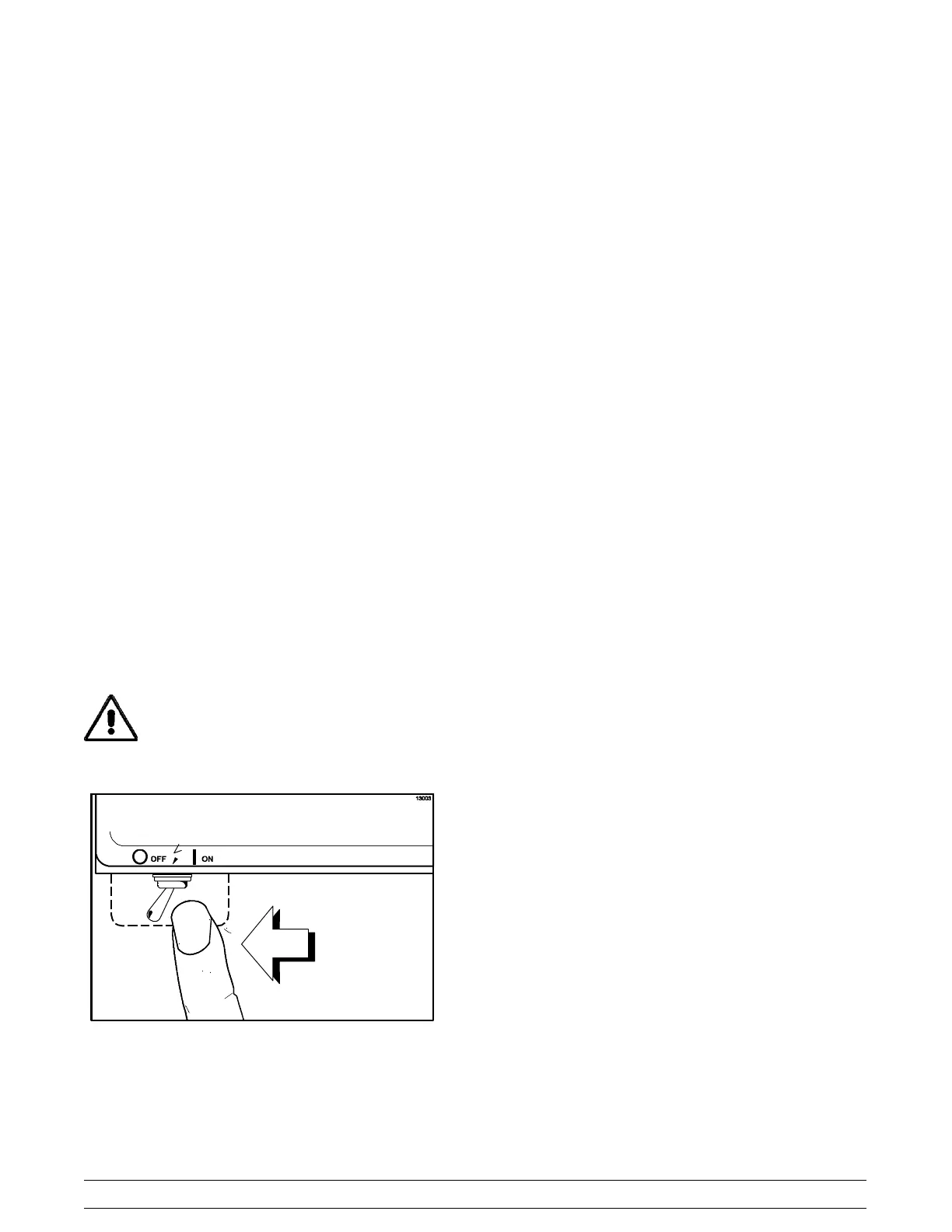
MAKE SURE POWER SWITCH IS IN THE
“OFF ” POSITION. Failure to do so may cause injury
from hazardous moving parts, or electrocution.
Figure 129
Step 1
Remove the syrup lines from the syrup ports, and
remove the restrictor cap from the bottom of the door
spout.
Step 2
Remove the spinner blade from the bottom of the door
spout by lifting up the plunger nut on the spinner
coupling and pulling down the blade.
Step 3
Remove the handscrews, freezer door , beater
assembly with drive shaft seal and scraper blades from
the freezing cylinder.
Step 4
Remove the drive shaft seal from the drive shaft of the
beater assembly.
Step 5
Remove the freezer door o- ring, front bearing, pivot
pin, draw handle and draw valve spinner assembly.
Remove o- ring from pivot pin.
Step 6
Disassemble the draw valve spinner assembly.
Remove the driven spinner by grasping the draw valve
and pulling the driven spinner out. Remove the spinner
shaft seal.
Step 7
Remove the two o- rings from the draw valve.
Step 8
From the shake pump cylinder, remove the retaining
pin, valve body, piston, spring and poppet, and the mix
inlet tube. Remove all o- rings and check rings.
Step 9
Remove the drive shaft from the drive hub in the rear
wall of the mix hopper. Remove the two small o- rings
and one large o- ring from the drive shaft.