29
Model PH90 Operating Procedures
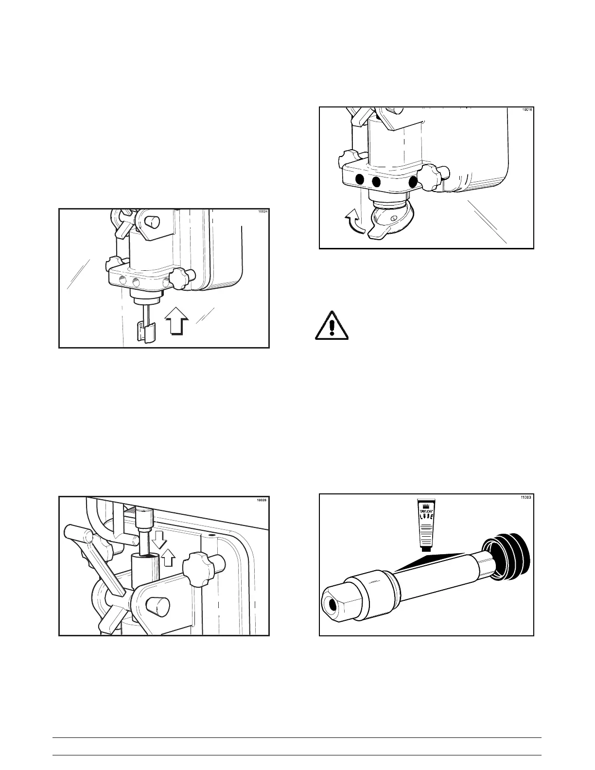
Step 17
Insert the spinner blade shaft from the bottom, into the
center of the driven spinner, and up through the draw
valve cavity until the shaft appears at the top of the
draw valve. The spinner blade must be aligned and
engaged to the driven spinner at the bottom. This
allows the spinner shaft to raise high enough to be
engaged into the spinner coupling at the top.
Figure 26
Step 18
Raise the locking collar of the spinner coupling and
insert the spinner shaft into the cavity of the coupling
until the locking collar can drop into the locked position.
Figure 27
Step 19
Snap the restrictor cap over the end of the door spout.
Figure 28
Freezing Cylinder Assembly -
Soft Serve Side
MAKE SURE POWER SWITCH IS IN THE
“OFF ” POSITION. Failure to do so may cause injury
from hazardous moving parts, or electrocution.
With the parts tray available for the soft serve side:
Step 1
Before installing the drive shaft, lubricate the groove
on the drive shaft. Slide the drive shaft seal over the
small end of the shaft and engage into the groove on
the shaft. Heavily lubricate the inside portion of the
seal and also lubricate the flat end of the seal that
comes in contact with the rear shell bearing. Apply an
even coat of lubricant to the shaft. DO NOT lubricate
the hex end.
Figure 29
Note: When lubricating parts, use an approved food
grade lubricant (example: Taylor Lube Hi
Performance).