6. STEERING SYSTEM
- 101 -
Fig. 6.55
Fig. 6.56
Fig. 6.57
Fig. 6.58
⑥
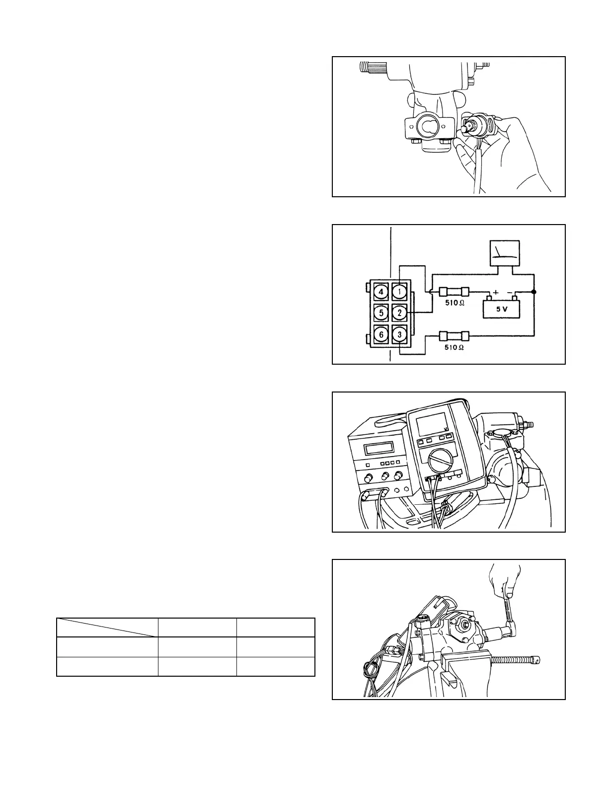
Apply grease to the roller of the potentiometer,
put the roller in the arm, and then install the
potentiometer by lightly tightening the fixing
screw.
⑦
Connect a tester, power supply unit, and
resistances to the connector of the potentiometer,
as shown in Fig. 6.56.
⑧
Turn the worm shaft clockwise and
counterclockwise several times, and measure the
voltage each time you leave your hand from the
shaft. If the following specied range are not
satised, adjust by turning the potentiometer.
Range to satisfy: 2.5 ± 0.1 V (main)
Range to satisfy: 2.5 ± 0.4 V (sub)
After adjustment is complete, fix the
potentiometer.
⑨
Measure the voltage obtained when the worm
shaft is turned to the left turning end and to the
right turning end.
Unit: V
Main Sub
Right turning end 1.2 – 1.6 0.9 – 1.9
Left turning end 3.4 – 3.8 3.1 – 4.1
VOLTMETER
(Sub) (Main)
 Loading...

