- 47 -
3. CONTROL SYSTEM
Fig. 3.7
2. CPU board and power supply board
The CPU board controls the controller and the power supply board supplies electric power to the
CPU board, FET power module drive circuit and sensors.
Visually check the CPU board and power supply board for scores, scratches, or undue discoloration,
and connectors for corrosion, observing the following conditions:
• Do not touch any components mounted on the surface of each printed circuit board with bare hand,
because it might be damaged by static electricity.
• Hold the edges of the printed circuit board when handling.
• Put them in an antistatic bag when transporting or storing.
(1) Removing CPU board or power supply board
WheninspectingorreplacingtheCPUboard,removethecasecoverrst,removethewireharness
connectorfrom theboard,removethe screws(9for securingtheCPUboard; 9forsecuringpower
supply board), and then detach the board from the base. When removing the connector, press the
connector lock securely and remove.
The CPU board and power supply board (including EPS board) inside the CPU box is connected with
three cables (between CN8 and CN2R, CN9 and CN1R, and CN6 and CN1E). After replacing the boards
with new ones, make sure to connect these cables completely.
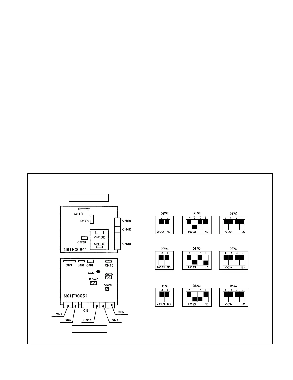
(2) Composition of CPU board and power supply board
* When setting the DSW on CPU board, refer to the
product specication.
The hatched parts represent switches.
* The DSW2 - 3 switches should be set to “ON” when
the truck is equipped with a seat switch.
(3) Default setting of DSW
<1-ton trucks>: All switches are OFF
<2-ton trucks>: DSW2-1 is ON and others are OFF.
Power supply board
CPU board
<3-ton trucks>: DSW2-2 is ON and others are OFF.
 Loading...

