3. CONTROL SYSTEM
- 48 -
3. Checking traveling/load handling power modules (TMDU, TMDV, TMDW, TMP)
(1) Composition of FET power module
MultipleFETsconnectedinparallelareconnectedinseriesverticallytoformahalfbridge.
Each FET lets electric current flow from the drain (D) to source (S) when a voltage is applied
between the gate (G) and source (S).
(2) Checking FET power module
①
Visually check the module for scores, scratches or excessive discoloration, and the connector for
corrosion.
②
Disconnect all the cables, bus bar, and capacitor board connected to the power module, and measure
the resistance of each terminal according to the table given below, using an analog tester set to a
resistance range of 1000 Ω.
③
Judgewhetherthemoduleisdefectiveornot,usingthemeasuredvaluesofresistance.
* The Normal values shown above should be used as a rough guide. The Normal value varies with
different types of tester and the internal battery’s state of charge.
* When checking the gates (G1, G2), you can check the gate device of any FET in the same row.
* When checking, observe the following conditions:
• Do not touch gate terminals (G1, G2) and components mounted on the power module with bare
hand;otherwisetheymightbedamagedduetostaticelectricity.
• Put the power module in an antistatic bag when carrying or storing. Do not give shock or vibration.
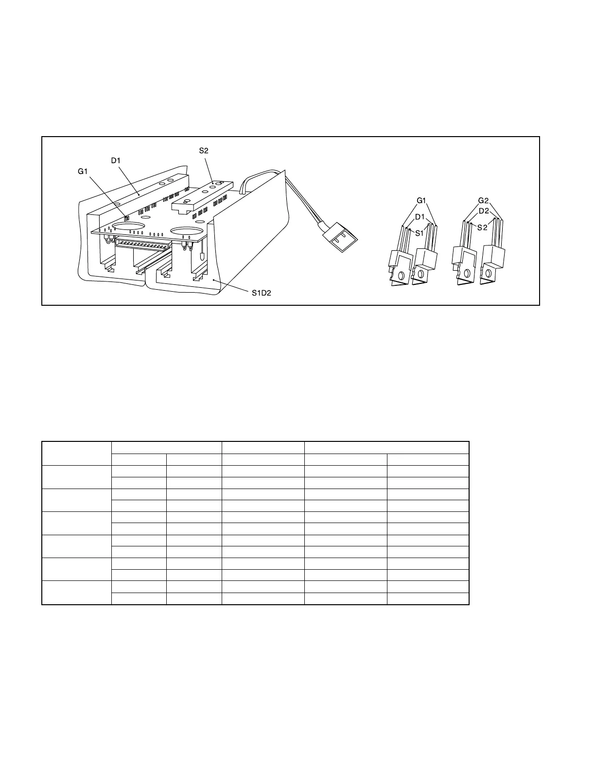
Fig. 3.8FETModule
Location to Tester Normal value
Judgment
be measured
(+) (–) Rough guide Good Not good
D1-S1D2 D1 S1D2 2 - 3 kΩ 2 - 3 kΩ 0 Ω and ∞Ω
S1D2 D1 ∞Ω ∞Ω below ∞Ω
S1D2-S2 S1D2 S2 2 - 3 kΩ 2 - 3 kΩ 0 Ω and ∞Ω
S2 S1D2 ∞Ω ∞Ω below ∞Ω
G1-S1D2 G1 S1D2 approx. 4 kΩ approx. 4 kΩ 0 Ω and ∞Ω
S1D2 G1 approx. 12 kΩ approx. 12 kΩ 0 Ω and ∞Ω
G2-S2 G2 S2 approx. 4 kΩ approx. 4 kΩ 0 Ω and ∞Ω
S2 G2 approx. 12 kΩ approx. 12 kΩ 0 Ω and ∞Ω
D1-G1 D1 G1 approx. 20 kΩ approx. 20 kΩ 0 Ω and ∞Ω
G1 D1 ∞Ω ∞Ω below ∞Ω
G2-S1D2 S1D2 G2 approx. 20 kΩ approx. 20 kΩ 0 Ω and ∞Ω
G2 S1D2 ∞Ω ∞Ω below ∞Ω
 Loading...

