70 Chapter 7 - Parameters Description User Manual
36 freq<thr2 Output frequency < than P.442 & P.443 values
37 HS temp=thr Heatsink temp = to P. 4 8 0 & P. 4 8 1 values
38 HS temp!=thr Heatsink temp
≠≠
≠≠
≠ of P. 4 8 0 & P. 4 8 1 values
39 HS temp>thr Heatsink temp > than P. 4 80 & P. 48 1 values
40 HS temp<thr Heatsink temp < than P. 4 80 & P. 48 1 values
41 Output freq Frequency in synchronism with output frequency
42 Out freq x 2 Frequency value x 2 in synchronism with output frequency
43 OutCoastThru Coast Through stopping
44 OutEmgStop Emergency stop
(*) see chapter 7.7, section PID Limit.
Code Name [Code] & Function. Default MIN MAX Unit Variation IP
I.100 Dig output 1 cfg See Digital Outputs selection list 0 0 44 112
The digital outputs are FACTORY set as follow:
Dig output 1 cfg - relay type (Terminal 1 - 2 - 3) = 0 Drive Ready
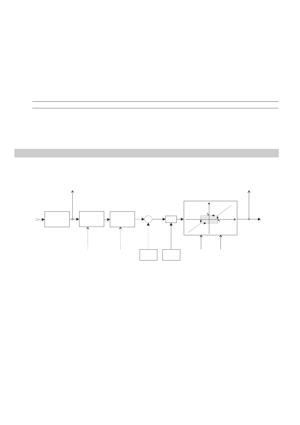
Analog Inputs Regulation Board
The drawing below, describes the block diagram of the standard "Analog Inputs" of the drive.
Terminal
10 bits+sign
converer
Filtro
T Delay
AN-INPUT
I 204
Offset
I 201
Monitor
d 202
Selection
Ref. Type
I 200
Gain
I 202
+
+
X
min
I 203
Clipping
I 205
I 203
I 205
OUT
IN
To Drive
Monitor
d 201
Figure 7.4.1: Analog Inputs
The regulation board provides as standard analog inputs.
Analog inputs resolution:
voltage input setting: 11 bits (10 bits + sign)
current input setting: 10 bits
A typical basis connection is reported in the figure 5.5.1.1.
The assignment of the Analog Inputs for a specific function, is described in the figure 7.5.1 at the menu FREQ
and RAMPS.
I.200 An In 1 type (Analog Input 1 type)
Setting of the Analog Input 1, in accordance with the type of reference control, available on its HW.
I.200 = 1 Unipolar +10V o 0-20mA
I.200 = 2 4-20mA