User Manual Chapter 7 - Parameters Description 71
I.201 An In 1 offset (Analog Input 1 offset)
I.202 An In 1 gain (Analog Input 1 gain)
Gain of the analog input.
It can be used to amplify or reduce the ratio between signal and controlled variable, or also to set different types
of control curves via analog reference, as described in the figures 7.4.2, 7.4.3 and 7.4.4.
Each parameters acts on the relative analog input.
I.203 An In 1 minimum (Analog Input 1 minimun)
It represents the minimum value of the parameter, on which the analog input is programmed (see figure 7.4.3).
Example: if the analog input 1 is programmed as speed reference, in this case I.203 represents the minimum
speed reference.
Each parameters acts on the relative analog input.
I.204 An In 1 filter (Analog Input 1 filter)
It is the response time of the signal reaction to the reference variations.
Each parameters acts on the relative analog input.
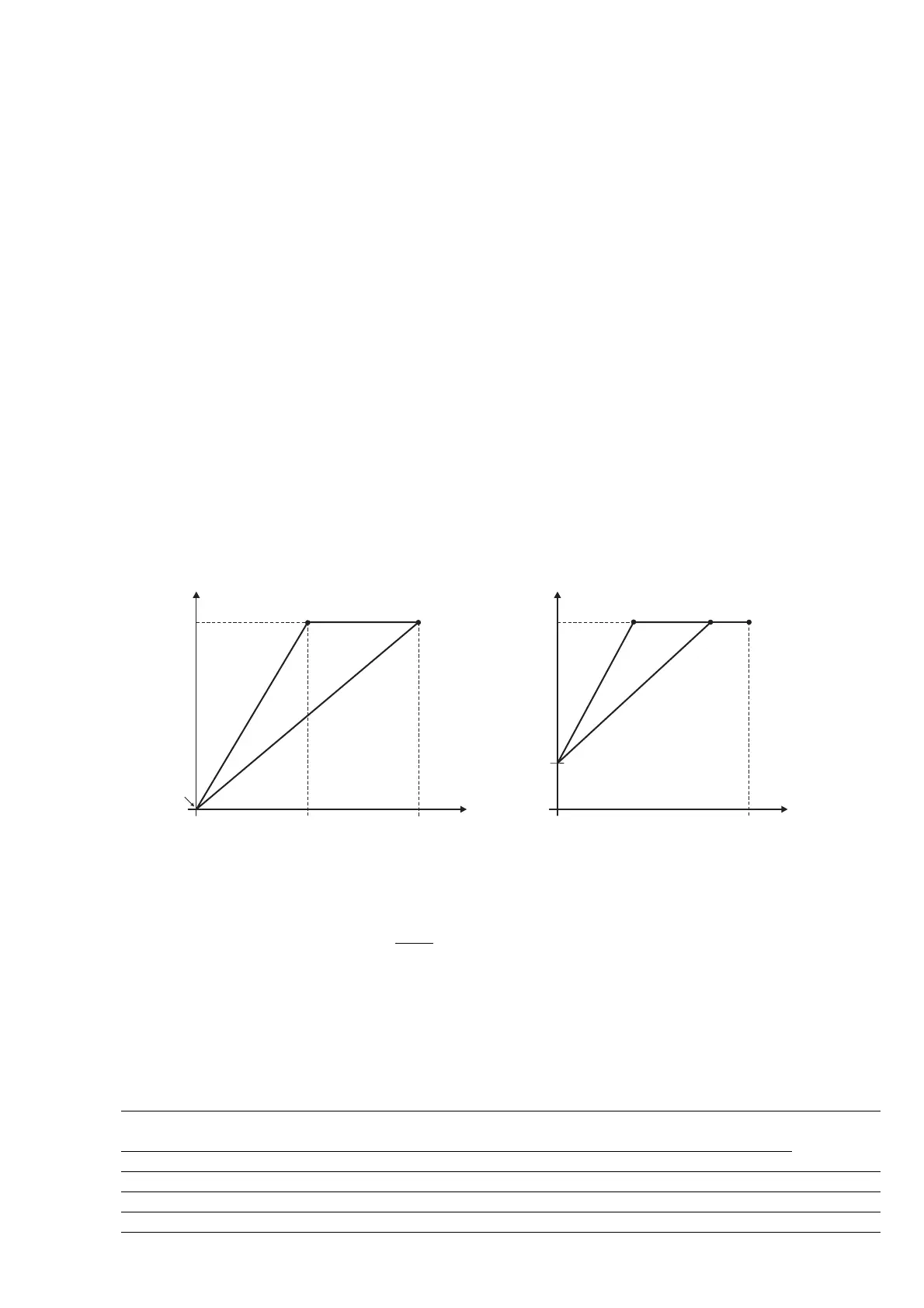
The use of the Analog Inputs parameters set, can be useful to customize the analog reference ratio.
In the figures below are reported some samples.
AnInp Drive
I.202=2
I.201
100%
5V
10V
I.202=1
AnInp Drive
I.202=2
I.201
100%
10V
I.202=1
Figure 7.4.2: Analog Input Scaling 1
An Inp Drive [%] = I.202 x An Inp [%] + x 100()
I.201
10
NOTE!
When the analog input reference is set at 0V, an eventual "noise" can cause undesired speed oscillation
between positive and/or negative values of I.203 parameter.
Code Name [Code] & Function. Default MIN MAX Unit Variation IPA
I.200 An in 1 Type [1] 0-10V / 0-20mA 1 0 1 118
[2] 4-20mA
I.201 An in 1 offset 0 -99.9 99.9 % 0.1 119
I.202 An in 1 gain 1 -9.99 9.99 % 0.01 120
I.203 An in 1 minimum 0 0 99.99 % 0.01 121
I.204 An in 1 filter 0.1 0.001 0.25 sec 0.001 122