SPIN TRAINER: Service & Maintenance Manual - rev. 2.0
Page 6.9
(1) Check whether the black and violet wires, which connect the alternator to pins 1 and 5 of CN2
on the alternator interface board, are correctly connected.
(2) Place the probes of an oscilloscope between the violet wire and the alternator ground. When
the speed is varied at 0% incline, the waveform frequency should vary as shown in the table
below:
SPEED
(Km/h)
FREQUENCY
(Hz)
10 81.6
15 122
20 164
25 204
30 245
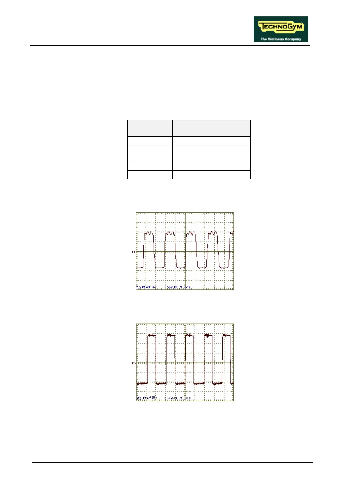
The signal at the alternator output and on connector CN2 of the alternator interface board
should be as shown below:
while on connectors CN1 of the alternator interface board and CN1 on the CPU board the
following square wave should be obtained:
(3) As for step (2) but with the oscilloscope probes between pins 1 (probe) and 5 (ground) of
connector CN2 on the alternator interface board.
(4) As for step (2) but with the oscilloscope probes between pins 5 (probe) and 3 (ground) of
connector CN1 on the alternator interface board.