SPIN TRAINER: Service & Maintenance Manual - rev. 2.0
Page 7.7
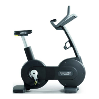
7.7. DISASSEMBLING THE FAN ASSEMBLY
Figure 7.7-1
Carry out the procedure described in paragraph
7.1. “Disassembling the display”.
1. Disconnect connector K3 from the fan
control board.
2. Unscrew the 2 self-tapping screws a using a
large Phillips screwdriver.
3. Remove the rear cover b of the display.
4. Remove the fan cable.
Figure 7.7-2
5. Unscrew the 4 screws c fixing the instruction
lexan d to the FAN ASSEMBLY bracket.
6. Unscrew the left-hand bracket e of the FAN
ASSEMBLY using a 5-mm hex T-wrench.
7. Cut the strap fixing the FAN cable on the
protective grill.
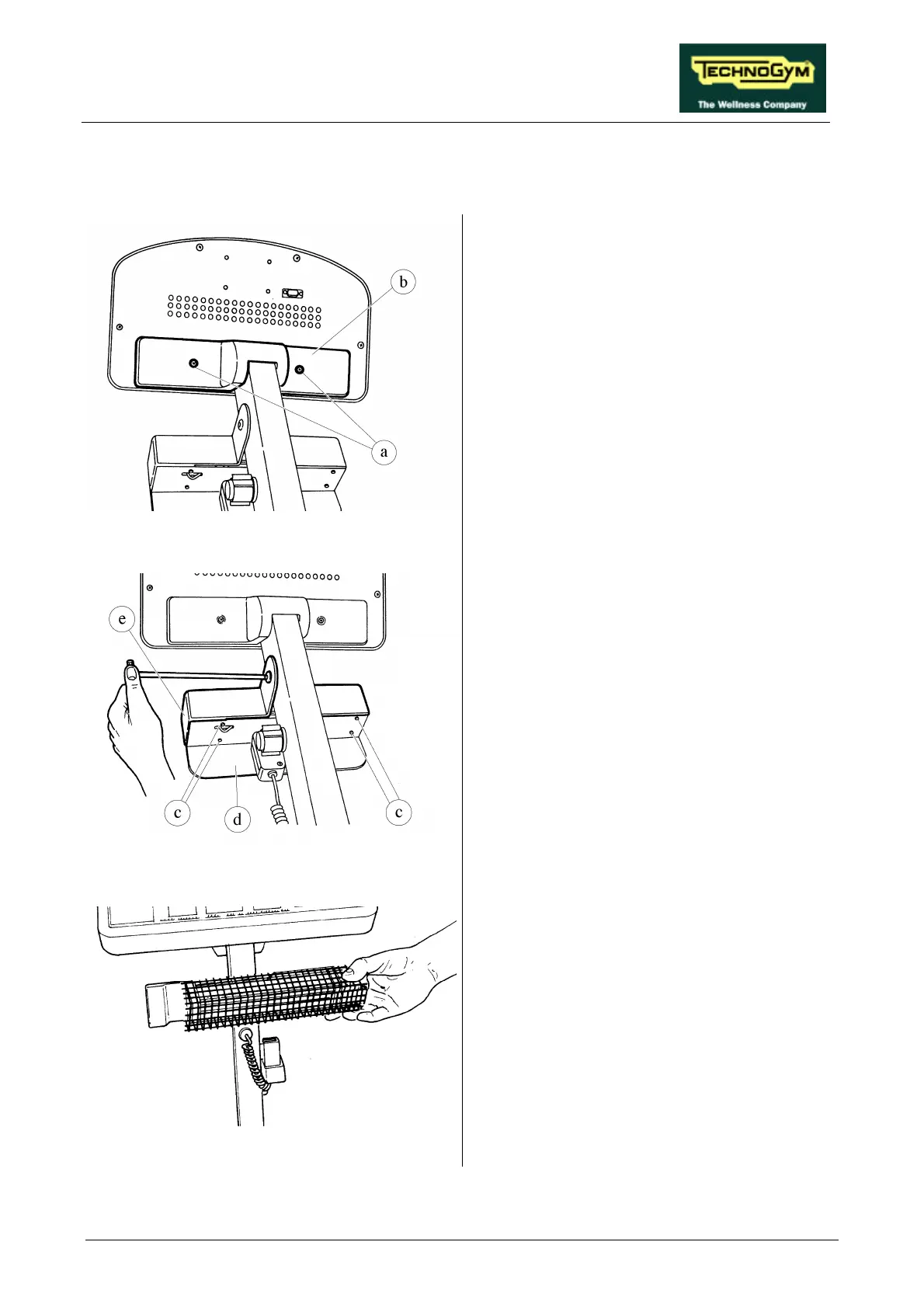
Figure 7.7-3
8. Remove the protective grill from the FAN
ASSEMBLY.
9. Remove the FAN.
To reassemble the FAN GROUP, carry out the
above procedure in reverse order.