SPIN TRAINER: Service & Maintenance Manual - rev. 2.0
Page 2.4
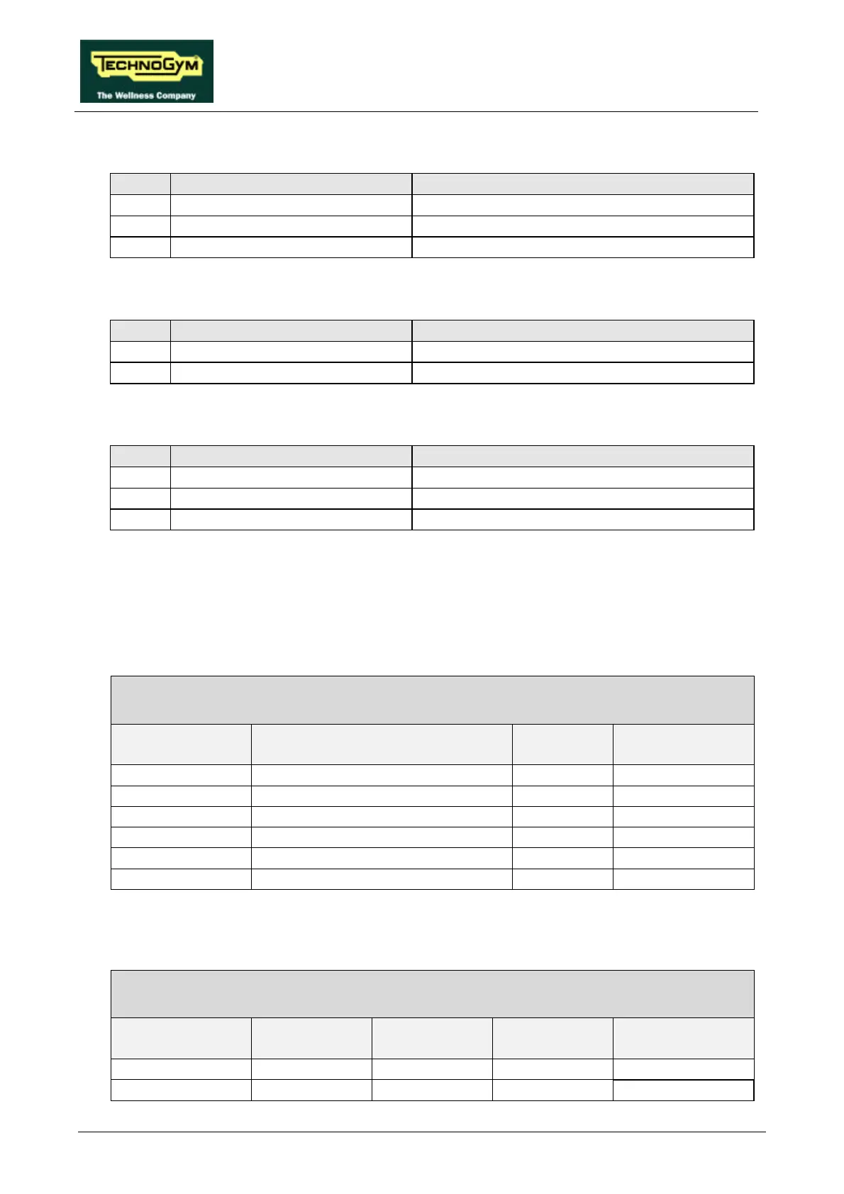
• Fan control board
name type of connector connection
K1 AMP MODU II 4-pin M. to CPU board (logic)
K2 AMP MODU II 2-pin M. to fan
K3 AMP MODU II 2-pin M. to CPU board and alternator (power)
• Power supply
name type of connector connection
CN1 PANDUIT 6-pin to mains power supply
CN2 PANDUIT 8-pin to alternator interface board
• Alternator interface board
name type of connector connection
CN1 AMP MATE-N-LOCK 15-pin F to CPU board
CN2 AMP MATE-N-LOCK 6-pin F to alternator
CN3 AMP MODU I 4-pin M. to power supply
2.6.2. WIRING
Cable SP-1 consists of 3 sections terminating in a connector that plugs into CN1 on the CPU board.
In the interests of simplicity, these 3 sections are described separately below:
SP-1: Internal connecting cable – machine control
CPU – Alternator interface board
CPU/CN1 Signal Color Alter. board/
CN1
1 +12 V Red 1
2 + 5 V Orange 2
3 ground Black 3
4 -12 V Blue 13
5 Alternator RPM X 6 Violet 5
6 Alternator control frequency Brown 6
On some machines, the signal designated +12 V in the above table is actually 10.5 V.
SP-1: Internal connecting cable – fan power supply
Fan control board – CPU – Alternator
Fan control
board / K3
Signal Color CPU/CN1 Alternator
1 +12 V Red - Resistor +
2 -12 V Blue 4 -