SPIN TRAINER: Service & Maintenance Manual - rev. 2.0
Page 2.5
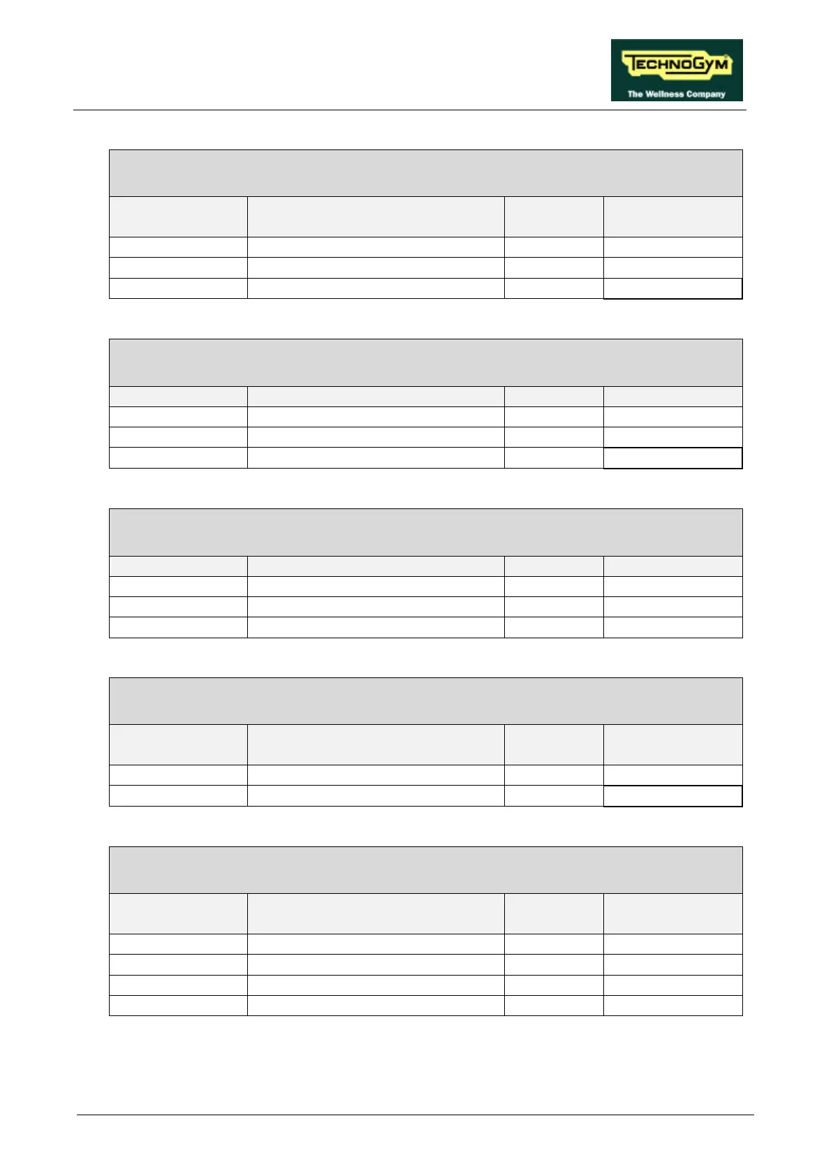
SP-1: Internal connecting cable – fan control
Fan control board – CPU
Fan control
board / K1
Signal Color CPU/CN1
2 ground Black 12
3 Fan enable Brown 10
4 +12 V Red 1
SP-8: Serial connector cable
CPU – Serial connector
CPU/CN2 Signal Color Serial connector
2 Tx Red 2
3 Rx Black 5
5 ground Orange 3
SP-7: Heart rate meter cable
CPU – Cardio receiver
CPU/CN4 Signal Color Receiver
1 +5 V Red 1
2 Pulse per beat Blue 2
3 ground Black 3
SP-10: Fan power supply cable
Fan control board – Fan
Fan control
board / K2
Signal Color Fan
1 Power supply Red 1
2 ground Blue 2
BK-6: Low voltage power supply cable
Power supply – Alternator interface board
Power supply
CN2
Signal Color Alter. interface
board / CN3
2 + 5 V Yellow 4
5 + 12 V Red 2
6-7-4 ground Black 3
8 - 12 V Blue 1