SPIN TRAINER: Service & Maintenance Manual - rev. 2.0
Page 2.6
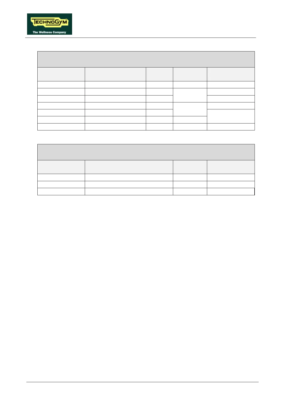
SP-5: Alternator cable
Alternator interface board – Alternator – Resistor
Alter. interface
board / CN2
Signal Color Alternator Resistor
1 Alternator RPM X 6 Violet Red eyelet 4 -
2 Resistor - Blue Yellow
Blue eyelet 6 Yellow eyelet 4
3 Resistor + Red Yellow
Red eyelet 6 Yellow
5 ground Black - eyelet 4
4 Excitation Orange Red Faston
SP-3: High voltage power supply
Power input socket – Power supply
Input socket Signal Color Power supply
CN1
Yellow Faston Ground Yellow 1
Red Faston Live Blue 4
Red Faston Neutral Black 6
The above is a simplified description of cable SP-3 and does not detail the ground node connections.