Technosoft 2019 16 iPOS360x VX-CAN/CAT Technical Reference
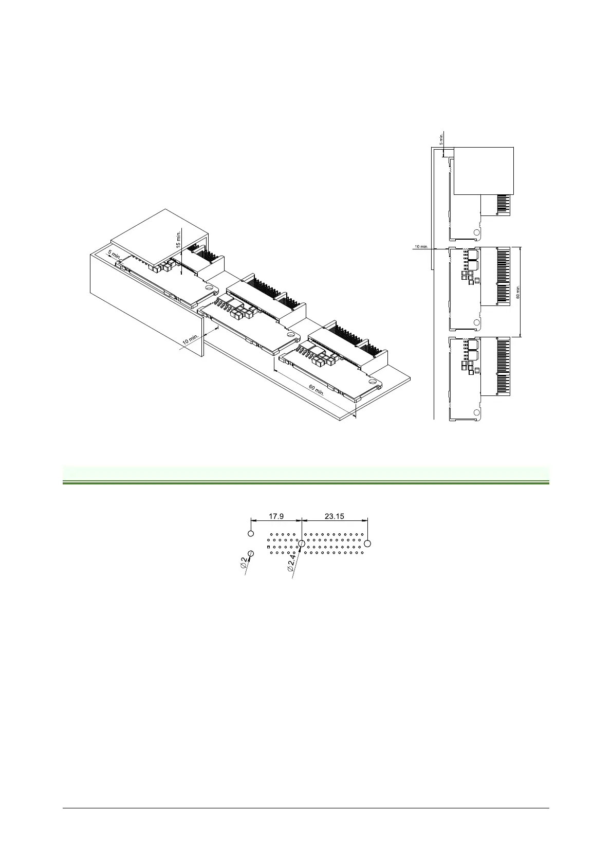
Figure 3.8 shows the recommended spacing to assure proper airflow by natural convection, in the worst case – closed
box done from a plastic (non-metallic) material with no ventilation openings.
Whenever possible, ventilation openings shall be foreseen.
Remark: In case of using a metallic box, with ventilation openings, all spacing values may be reduced substantially.
With proper ventilation, keeping the air surrounding the iPOS360x inside the limits indicated in Figure 3.35 and Figure
3.40 the spacing values may be reduced down to the mechanical tolerance limits of Figure 3.2.
Figure 3.7 iPOS360X VX-CAN Recommended spacing for horizontal mounting, worst case: non-metallic, closed box
3.4 Motherboard PCB Design
The iPOS360x drive, when plugged vertically into the recommended mating connector and retainer, has the following
PCB footprint:
Figure 3.8 PCB footprint of mating connector and retainer
It is recommended to use a multi-layer PCB for the motherboard, in order to have enough room for routing all the pins
of the iPOS360X. Using a 2-layer PCB is possible when some of the iPOS360X pins remain un-connected.
Below is a list of recommendations for the PCB design of the motherboard:
• Motor supply and motor outputs: use islands / areas of copper to escape connector areas; this will maximize
current capability. When using simple tracks, use at least 50mil cross section (35mil track width for 1oz/ft
2
copper thickness)
• Motor supply and ground return tracks between iPOS360X and the nearby V
MOT
decoupling capacitor are to
be considered as EMI sources, and kept to a minimum length.
• Place the decoupling capacitors on V
MOT
and V
LOG
(see also 3.7.8 Power Supply Connection) as close as
physically possible to the iPOS360X, to minimize EM radiated emissions. For un-shielded applications (no
metallic box) and typical EMC regulations, the spacing between iPOS360X and capacitors must be less than
3 centimeters.
• In multi-axis applications (multiple iPOS360X drives on the same motherboard), it is preferable to have a
separate decoupling capacitor for each drive’s V
MOT
. For V
LOG
it is acceptable to share one decoupling
capacitor for two drives.