Technosoft 2019 35 iPOS360x VX-CAN/CAT Technical Reference
3.7.10 CAN-bus connection (for CAN drives only)
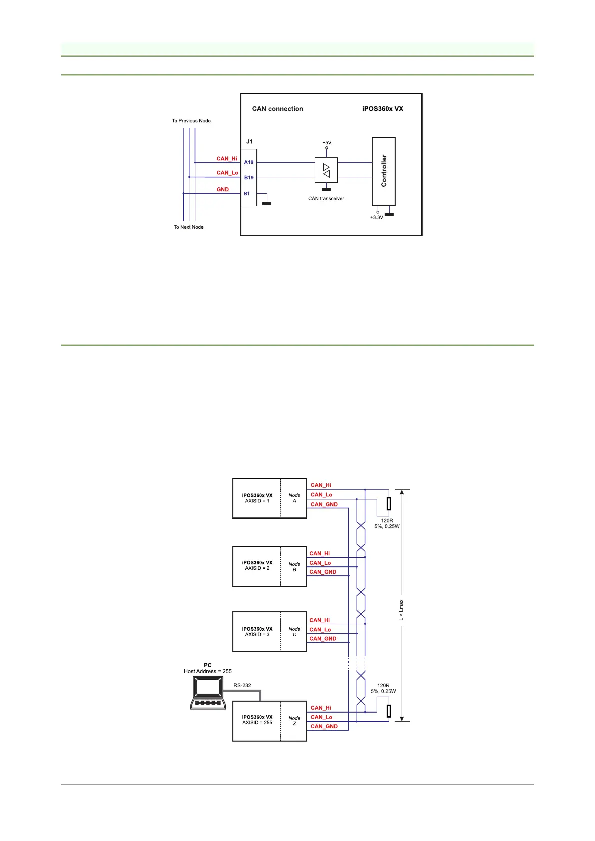
3.7.10.1 CAN connection
Figure 3.30. CAN connection
Remarks:
1. The CAN network requires a 120-Ohm terminator. This is not included on the board.
Figure 3.32 shows how to connect it on your network
2. CAN signals can sustain up to +/-58V without damage.
3.7.10.2 Recommendation for wiring
a) Build CAN network using cables with twisted wires (2 wires/pair), with CAN-Hi twisted together with CAN-Lo.
It is recommended but not mandatory to use a shielded cable. If so, connect the shield to GND. The cable
impedance must be 105 ... 135 ohms (120 ohms typical) and a capacitance below 30pF/meter.
b) When using a printed circuit board (PCB) motherboard based on FR-4 material, build the CAN network using
a pair of 12mil (0.012”) tracks, spaced 8 to 10mils (0.008”…0.010”) apart, placed over a local ground plane
(microstrip) which extends at least 1mm left and right to the tracks.
c) Whenever possible, use daisy-chain links between the CAN nodes. Avoid using stubs. A stub is a "T"
connection, where a derivation is taken from the main bus. When stubs can’t be avoided keep them as short
as possible. For 1 Mbit/s (worst case), the maximum stub length must be below 0.3 meters.
d) The 120Ω termination resistors must be rated at 0.2W minimum. Do not use winded resistors, which are
inductive.
Figure 3.31. Multiple-Axis CAN network