Technosoft 2019 45 iPOS360x VX-CAN/CAT Technical Reference
3.10.13 Encoder Inputs (A+, A-, B+, B-, Z+, Z-,)
1
Single-ended mode compliance
Leave negative inputs disconnected
TTL / CMOS / Open-collector
Input voltage, single-ended mode A/A+,
B/B+
V
Floating voltage (not connected)
Input voltage, single-ended mode Z/Z+
V
Floating voltage (not connected)
Input current, single-ended mode A/A+,
mA
Logic “HIGH”; Internal 2.2KΩ pull-up to +5
Differential mode compliance
For full RS422 compliance, see
2
Input voltage, differential mode
V
Common-mode range (A+ to GND, etc.) -7 +7
Input impedance, differential
kΩ
Input frequency
Single-ended mode, Open-collector / NPN
Differential mode, or Single-ended driven by push-pull (TTL /
CMOS)
0 10
MHz
Minimum pulse width
Single-ended mode, Open-collector / NPN
Differential mode, or Single-ended driven by push-pull (TTL /
CMOS)
50 ns
Input voltage, any pin to GND
Absolute maximum values, continuous
Absolute maximum, surge (duration ≤ 1s)
†
-11 +14
3.10.14 RS-232
Depending on software settings
3.10.15 CAN-Bus (for CAN drives)
ISO11898, CiA-301v4.2, 402v3.0
Bus length
m
Node addressing
Hardware ( CANopen selection pin)
127 (CANopen);
255 (TMLCAN);
1 - 127 (CANopen); 1- 255 (TMLCAN)
Voltage, CAN-Hi or CAN-Lo to GND
3.10.16 Supply Output (+5V)
+5V output current
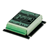
iPOS360X VX-CAT with ECAT-VX adapter
120 200 210
mA
Yes / Drive resets at event
1
Encoder differential input pins do not have internal 120Ω termination resistors connected across
2
For full RS-422 compliance, 120Ω termination resistors must be connected across the differential pairs, as close as possible to the
drive input pins. See Figure 3.16. Differential incremental encoder connection