Technosoft 2019 33 iPOS360x VX-CAN/CAT Technical Reference
J
M
– total rotor inertia [kgm
2
]
J
L
– total load inertia as seen at motor shaft after transmission [kgm
2
]
ϖ
M
– motor angular speed before deceleration [rad/s]
m
M
– motor mass [kg] – when motor is moving in a non-horizontal plane
m
L
– load mass [kg] – when load is moving in a non-horizontal plane
g
– gravitational acceleration i.e. 9.8 [m/s
2
]
h
initial
– initial system altitude [m]
h
final
– final system altitude [m]
I
M
– motor current during deceleration [A
RMS
/phase]
R
Ph
– motor phase resistance [Ω]
t
d
– time to decelerate [s]
T
F
– total friction torque as seen at motor shaft [Nm] – includes load and transmission
In case of a linear motor and load, the motor inertia J
M
and the load inertia J
L
will be replaced by the motor mass and
the load mass measured in [kg], the angular speed
ϖ
M
will become linear speed measured in [m/s] and the friction
torque T
F
will become friction force measured in [N].
Option 2. Connect a chopping resistor R
CR
between phase CR/B- and ground, and activate the software option of
dynamic braking (see below).
This option is not available when the drive is used with a step motor.
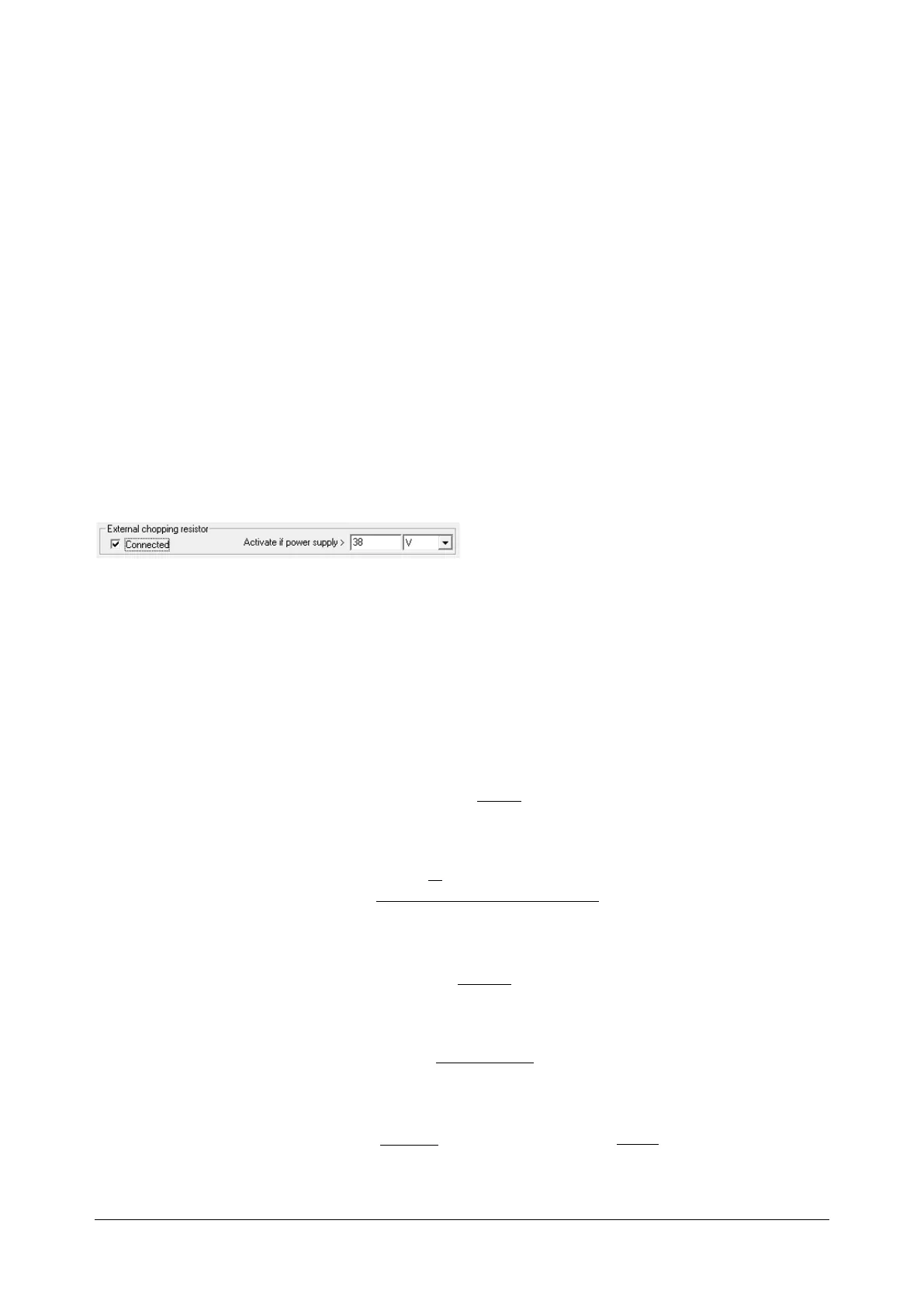
The chopping resistor option can be found in the Drive Setup dialogue within EasyMotion / EasySetup.
The chopping will occur when DC bus voltage increases over U
CHOP
. This parameter (U
CHOP
) should be adjusted
depending on the nominal motor supply. Optimally (from a braking point of view), U
CHOP
should be a few volts above
the maximum nominal supply voltage. This setting will activate the chopping resistor earlier, before reaching dangerous
voltages – when the over-voltage protection will stop the drive. Of course, U
CHOP
must always be less than U
MAX
– the
over-voltage protection threshold.
Remark: This option can be combined with an external capacitor whose value is not enough to absorb the entire
regenerative energy E
M
but can help reducing the chopping resistor size.
Chopping resistor selection
The chopping resistor value must be chosen to respect the following conditions:
1. to limit the maximum current below the drive peak current I
PEAK
= 10A
2. to sustain the required braking power:
d
CHOPMAXM
CR
t
UUCE
P
)(
2
1
2
2
−−
=
where C is the capacitance on the motor supply (external), i.e:
3. to limit the average current below the drive nominal current I
NOM
=0.9A
where t
CYCLE
is the time interval between 2 voltage increase cycles in case of repetitive moves.
4. to be rated for an average power
and a peak power
Remarks: