EasyManua.ls Logo

TECHTOP TD350 - Page 169

TECHTOP TD350
371 pages
Print Icon
To Next Page IconTo Next Page
To Previous Page IconTo Previous Page
Loading...
TD350 Series VFD Function parameter list
-164-
Function
code
Name
Detailed parameter description
Default
value
Modify
P05.14
S2 terminal
switch-on delay
Si electrical level
Si valid
invalid invalid
Switcn-on
delay
Switcn-off
delay
valid
Setting range: 0.00050.000s
Note: After a virtual terminal is enabled, the state of
the terminal can be changed only in communication
mode. The communication address is 0x200A.
0.000s
P05.15
S2 terminal
switch-off delay
0.000s
P05.16
S3 terminal
switch-on delay
0.000s
P05.17
S3 terminal
switch-off delay
0.000s
P05.18
S4 terminal
switch-on delay
0.000s
P05.19
S4 terminal
switch-off delay
0.000s
P05.20
HDIA terminal
switch-on delay
0.000s
P05.21
HDIA terminal
switch-off delay
0.000s
P05.22
HDIB terminal
switch-on delay
0.000s
P05.23
HDIB terminal
switch-off delay
0.000s
P05.24
Lower limit value
of AI1
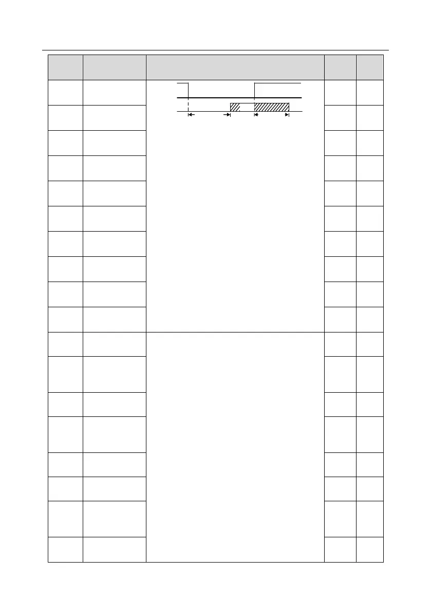
These function codes define the relation between
analog input voltage and corresponding set value of
analog input. When the analog input voltage
exceeds the range of max./min. input, the max.
input or min. input will be adopted during
calculation.
When analog input is current input, 020mA current
corresponds to 010V voltage.
In different applications, 100% of analog setting
corresponds to different nominal values.
The figure below illustrates several settings.
0.00V
P05.25
Corresponding
setting of lower
limit of AI1
0.0%
P05.26
Upper limit value
of AI1
10.00V
P05.27
Corresponding
setting of upper
limit of AI1
100.0%
P05.28
Input filter time of
AI1
0.030s
P05.29
Lower limit value
of AI2
-10.00V
P05.30
Corresponding
setting of lower
limit of AI2
-100.0
%
P05.31
Intermediate
value 1 of AI2
0.00V

Table of Contents

Other manuals for TECHTOP TD350

Related product manuals