Operation
TRIGGER 50 Q
LEVEL OVERLOAD
INDICATOR INDICATION
TRIGGER
---,--,-~-,----,--,l-'--r-----r--'
SWEEP
CURRENTLY
-+h.=
......
~.
l!~SE~2,..=·······~-=-~~~~Ii.iiW'~
DELAY TIME
UNDER CONTROL f-I······ - DELTA VOLTAGE
(A
or B)
S~iZ:ATi~~E
INVERT
INDICATOR
(1)
t
BANDWIDTH
LIMIT
INDICATOR
(BWL)
CHANNEL 3
SCALE
FACTOR
A SWEEP
SCALE
FACTOR
5854-03
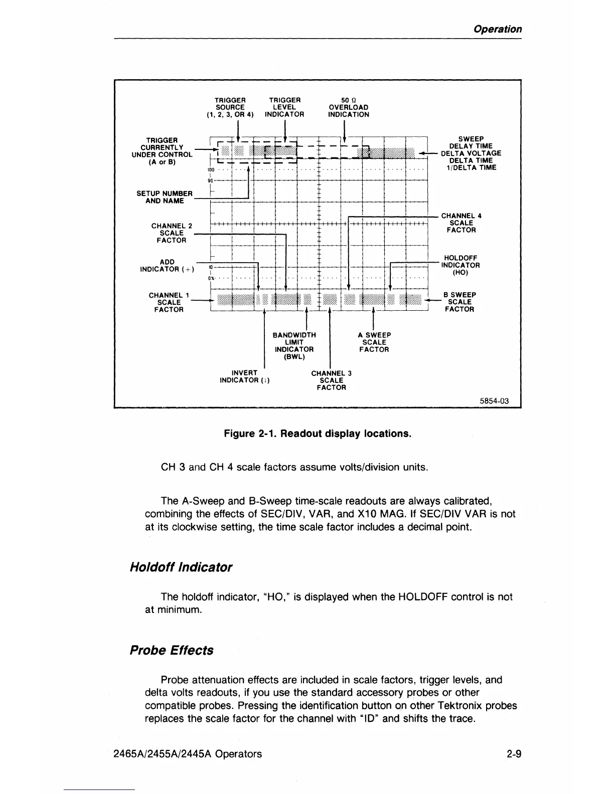
Figure 2-1. Readout display locations.
CH
3 and
CH
4 scale factors assume volts/division units.
The
A-Sweep and B-Sweep time-scale readouts are always calibrated,
combining the effects of
SEC/DIV, VAR, and X10 MAG. If SEC/DIV VAR
is
not
at its
clockwise setting, the time scale factor includes a decimal point.
Holdoff Indicator
The holdoff indicator, "HO,"
is
displayed when the HOLDOFF control
is
not
at minimum.
Probe Effects
Probe attenuation effects are included
in
scale factors, trigger levels, and
delta volts readouts, if you use the standard accessory probes or other
compatible probes. Pressing the identification button on other Tektronix probes
replaces the scale factor for the channel with "10" and shifts the trace.
2465A/2455A/2445A Operators
2-9