Applications
1.
Press A/B/MENU to display the main
CIT
Menu.
2.
Turn
Ll
to select COUNT, then press the upper Trigger MODE button.
3. Turn
Ll
to select FREQ or PERIOD, then press the upper MODE button.
4.
The readout will automatically show the frequency or period of the
A-
Trigger signal, up to 150 MHz, until a conflicting function
is
selected or the
function
is
cancelled by pressing AUTO Setup or by selecting the Menu
and
pressing the lower Trigger Mode button.
Rise Time
and
Fall Time
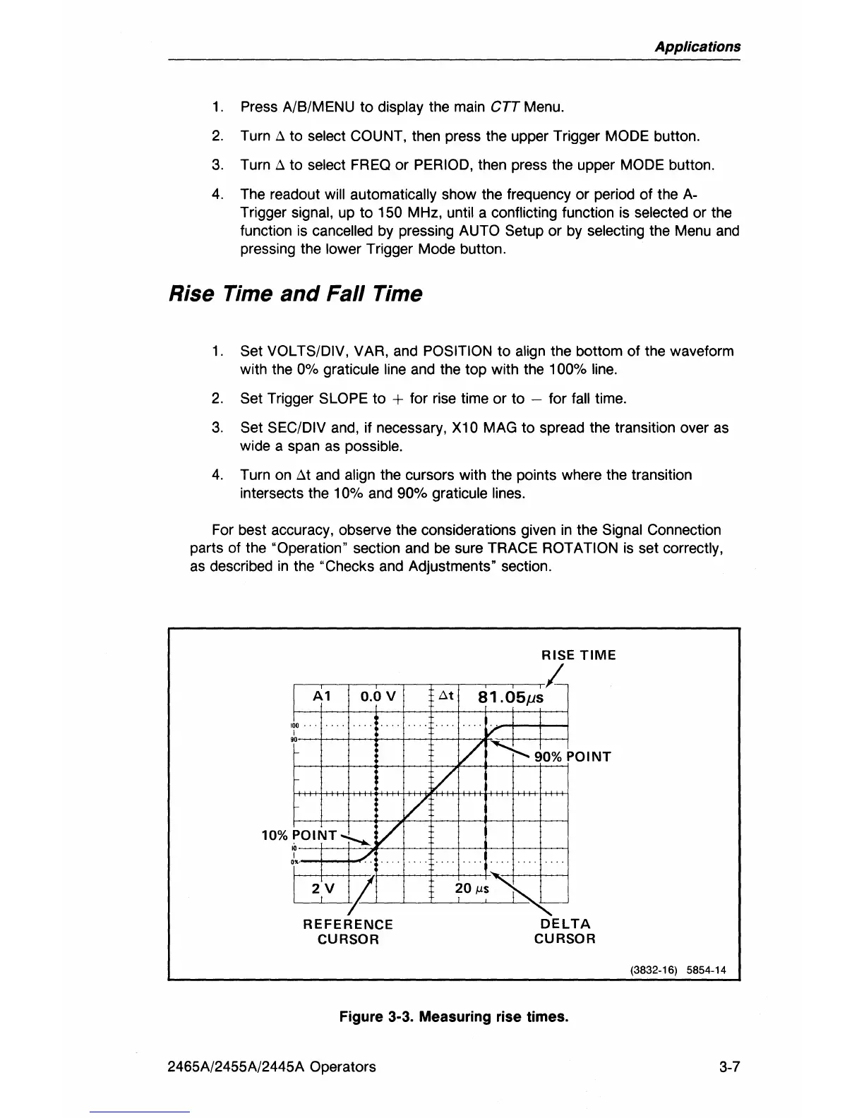
1.
Set VOLTS/DIV, VAR, and POSITION to align the bottom of the waveform
with the
0%
graticule
line
and
the top with the 100%
line.
2.
Set Trigger SLOPE to + for rise time or to - for fall time.
3.
Set SEC/DIV
and,
if necessary, X10 MAG to spread the transition over
as
wide a span
as
possible.
4.
Turn
on
Llt
and
align the cursors with the points where the transition
intersects the
10%
and
90% graticule lines.
For best accuracy, observe the considerations given
in
the Signal Connection
parts of the "Operation" section
and
be
sure TRACE ROTATION
is
set correctly,
as
described
in
the "Checks
and
Adjustments' section.
10%
A1
0.0
V
I~O
.•
1
"
POINT--:-..
~
./
I'
..
V
~
7
REFERENCE
CURSOR
Z
RISE
TIME
I-
At
81.05ps
V
L
~~O%P
OINT
V
-
20
!,S
~
-
DELTA
CURSOR
Figure
3-3_
Measuring rise times.
2465A/2455A/2445A Operators
(3832-16) 5854-14
3-7