Applications
Peak-to-Peak Voltage
With
~
V turned
on
and
VOL TS/DIV VAR fully clockwise, align the
~
REF
cursor
with the bottom of a waveform and align the
~
cursor with the top. The readout
shows the equivalent voltage between the cursors anywhere
on
a waveform.
Accuracy
is
degraded at frequencies approaching the instrument bandwidth.
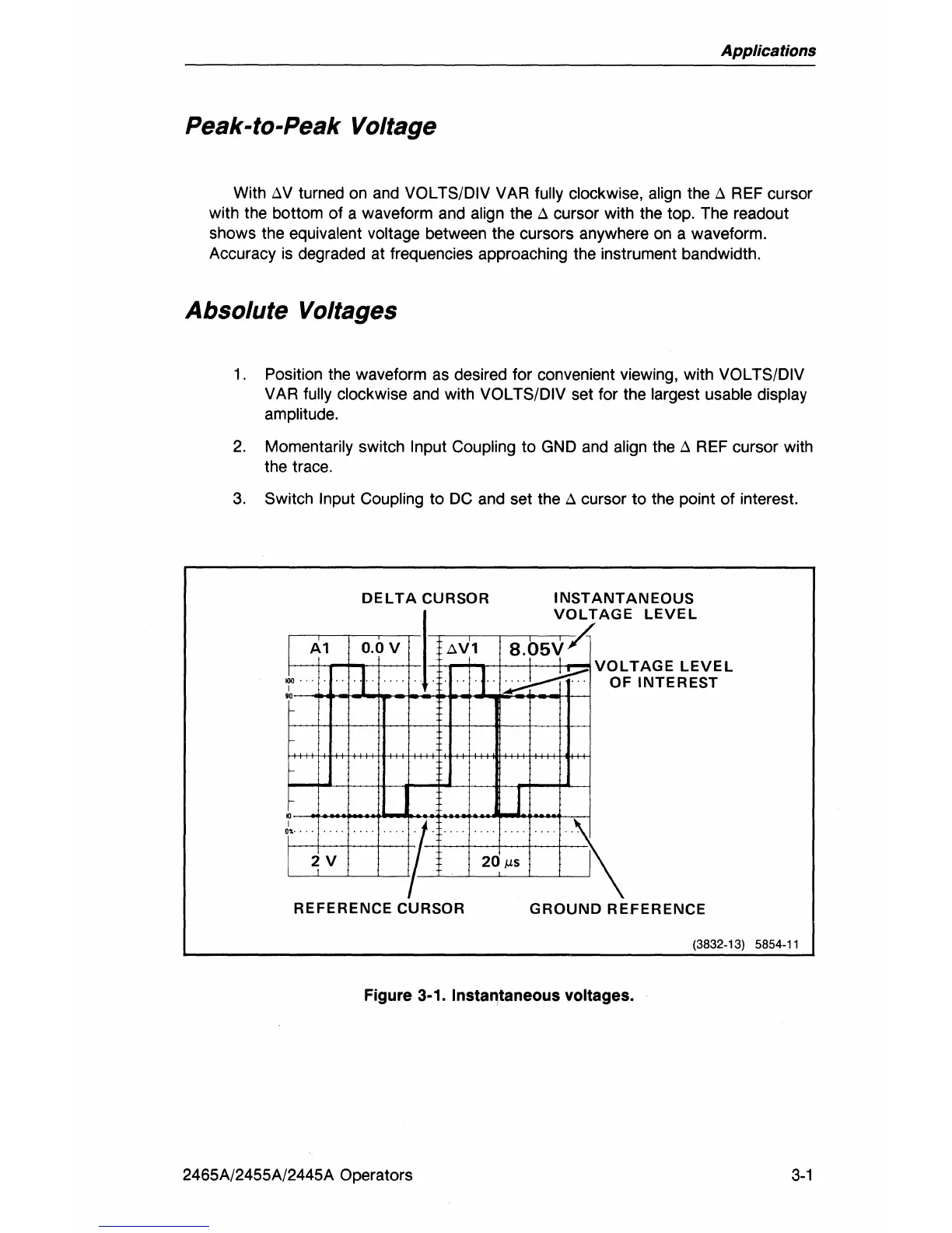
Absolute Voltages
1.
Position the waveform
as
desired for convenient viewing, with VOL TS/DIV
VAR fully
clockwise
and
with VOL TS/DIV set for the largest usable display
amplitude.
2.
Momentarily switch Input Coupling to
GND
and
align the
~
REF
cursor with
the trace.
3.
Switch Input Coupling to
DC
and
set the
~
cursor to the point of interest.
DELTA
CURSOR
I
Al
0.0
V
AVl
Jo.
-I
J
I
90
•
I
or'
I NST
ANT
AN
EOUS
VOLTAGE
LEVEL
8.05V
Yl'
.d--tr
J
VOLTAGE
LEVEL
OF
INTEREST
2V
20
iLS
REFERENCE
CURSOR
GROUND
REFERENCE
(3832-13) 5854-11
Figure 3-1. Instantaneous Voltages.
2465A/2455A/2445A Operators
3-1