Applications
CH
1
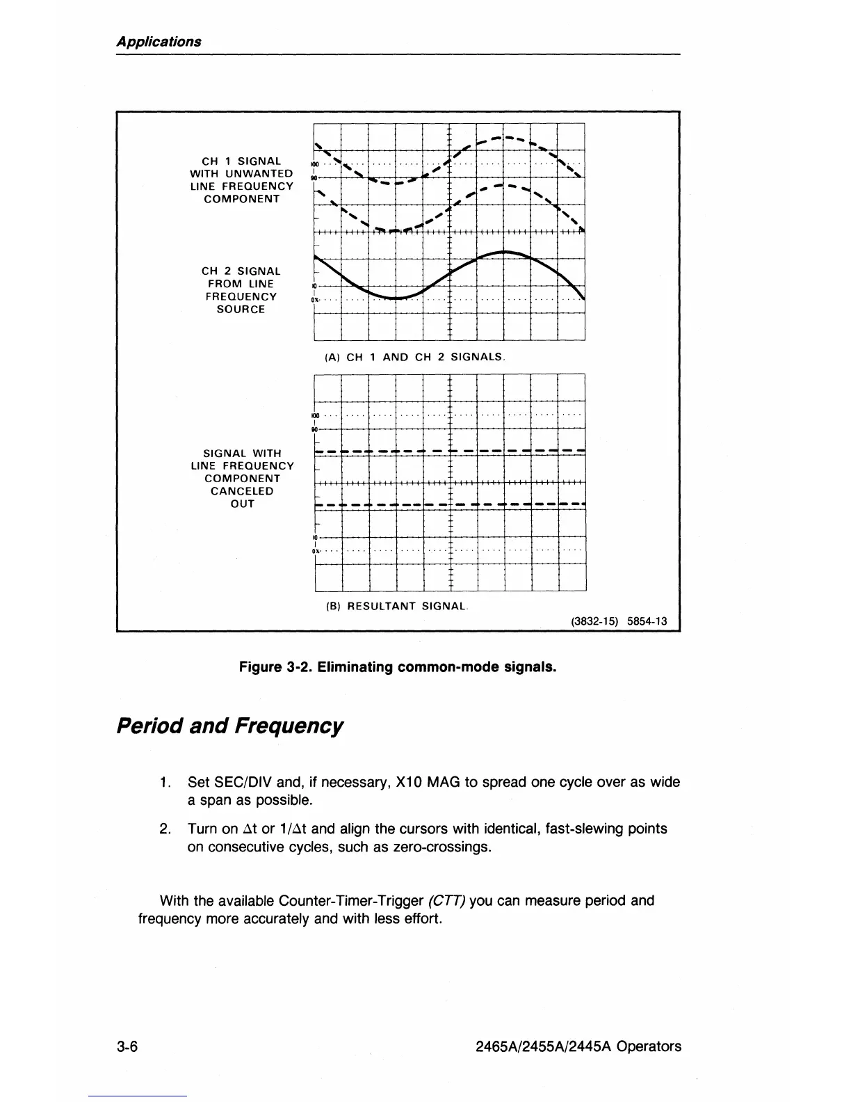
SIGNAL
WITH
UNWANTED
LINE
FREQUENCY
COMPONENT
CH 2
SIGNAL
FROM
LINE
FREQUENCY
SOURCE
,f.--
--
.i,'~
....
. .
"-';
"
1'
..
I
"
..
-
...-
"
"
- ...
"',
' ...
,
...
..
...
,."
-
-
.""
.......
./
V
..........
r-...
.
I
:\
"t'.
(AI
CH
1
AND
CH
2
SIGNALS
.i,
~--4-~--~--~-r--~-+--+--+~
SIGNAL
WITH
FI-~-~~-==F~-4-=----=t"":::-F-=t=-=r-:..=-t-=--=-'=r
--:="-"1-
LINE
FREQUENCY
COMPONENT
CANCELED
OUT
~-
- -
--1---
--
--~-
'r--+---1--+-t-+--t--+---t--t--l
"t"
(BI
RESULTANT
SIGNAL
(3832-15) 5854-13
Figure 3-2. Eliminating common-mode signals.
Period
and
Frequency
3-6
1,
Set SEC/DIV and, if necessary, X10 MAG to spread one cycle over as wide
a span as
possible.
2.
Turn on
t.t
or 1/t.t and align the cursors with identical, fast-slewing points
on consecutive
cycles, such as zero-crossings.
With the
available Counter-Timer-Trigger
(CIT)
you can measure period and
frequency more
accurately and with less effort.
2465A/2455A/2445A Operators