SETUP
~
STEP/
0Y----[j
Controls, Connectors,
and
Indicators
,
CHOPI
ALT
-@
o
0--,--
17
''\
6014-03
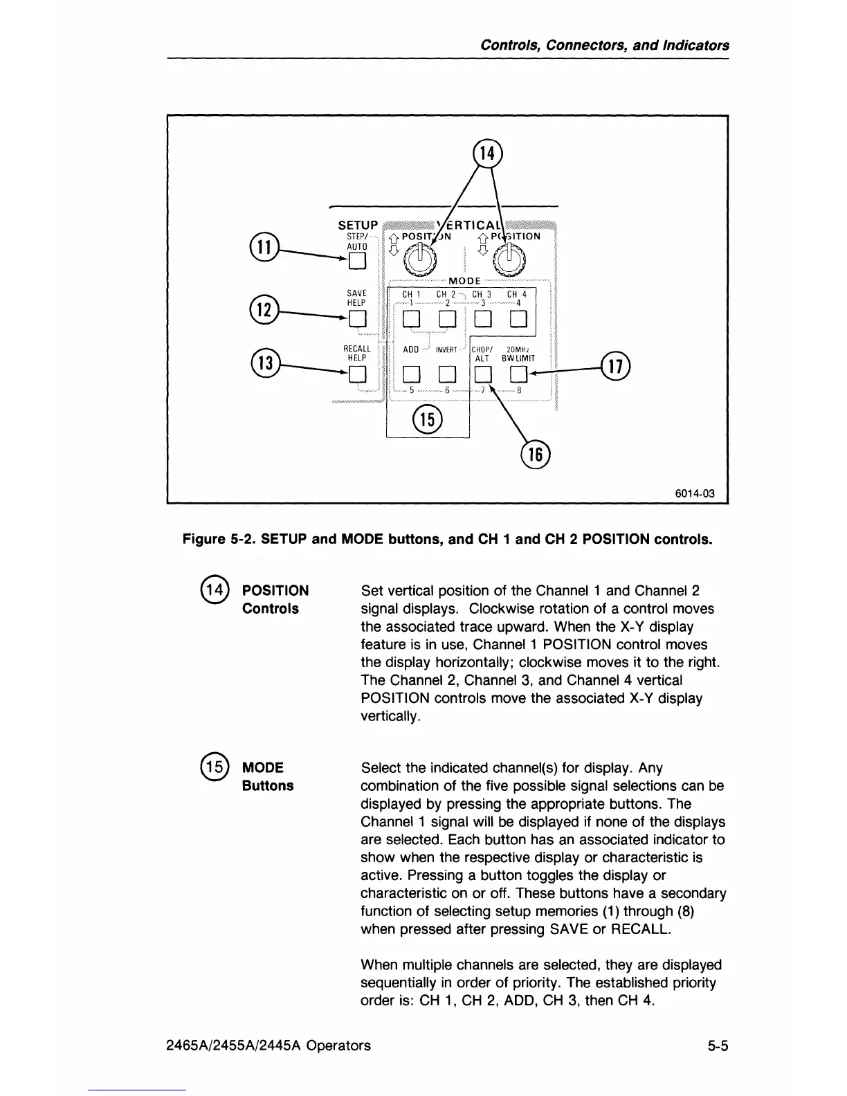
Figure 5-2. SETUP and MODE buttons, and CH 1 and
CH
2 POSITION controls.
@ POSITION
Controls
@
MODE
Buttons
Set vertical position of the Channel 1 and Channel 2
signal displays. Clockwise rotation of a control moves
the associated trace upward. When the
X-
Y display
feature
is
in use, Channel 1 POSITION control moves
the
display horizontally; clockwise moves it
to
the right.
The
Channel
2,
Channel
3,
and Channel 4 vertical
POSITION controls
move the associated X-V display
vertically.
Select the indicated channel(s) for display. Any
combination of the five
possible signal selections can
be
displayed by pressing the appropriate buttons. The
Channel 1 signal will
be
displayed if none of the displays
are selected. Each button has
an
associated indicator to
show when the respective
display
or
characteristic
is
active. Pressing a button toggles the display
or
characteristic on or off. These buttons have a secondary
function
of
selecting setup memories (1) through (8)
when pressed after pressing SAVE
or
RECALL.
When
multiple channels are selected, they are displayed
sequentially
in
order
of
priority. The established priority
order is:
CH
1,
CH
2,
ADD,
CH
3,
then
CH
4.
2465A/2455A/2445A Operators
5-5