1
MO
DC
500
DC
CH
1 OR X
and
CH
2
Input
Controls, Connectors,
and
Indicators
All
frequency components of the input signal are
coupled
to
the vertical. Input resistance
is
1
Mil
to
ground.
All
frequency components of the input signal are
coupled to the vertical, with the input terminated by
50 II
to
ground. If excessive signal is applied to
either the
CH
1 or the
CH
2 input connector while
50 II
DC
input coupling
is
selected, input coupling will
revert
to
1
Mil
GND
and a CRT readout will indicate
the
overloaded condition. Changing the input
coupling of the affected channel removes the
overload message.
Conduct
external signals
to
the Channel 1 and Channel
2 vertical inputs. A signal applied
to
the
CH
1
OR
X
connector provides the
horizontal deflection for
an
X-
Y
display.
Each
connector includes a coding-ring contact
for Tektronix-coded probes.
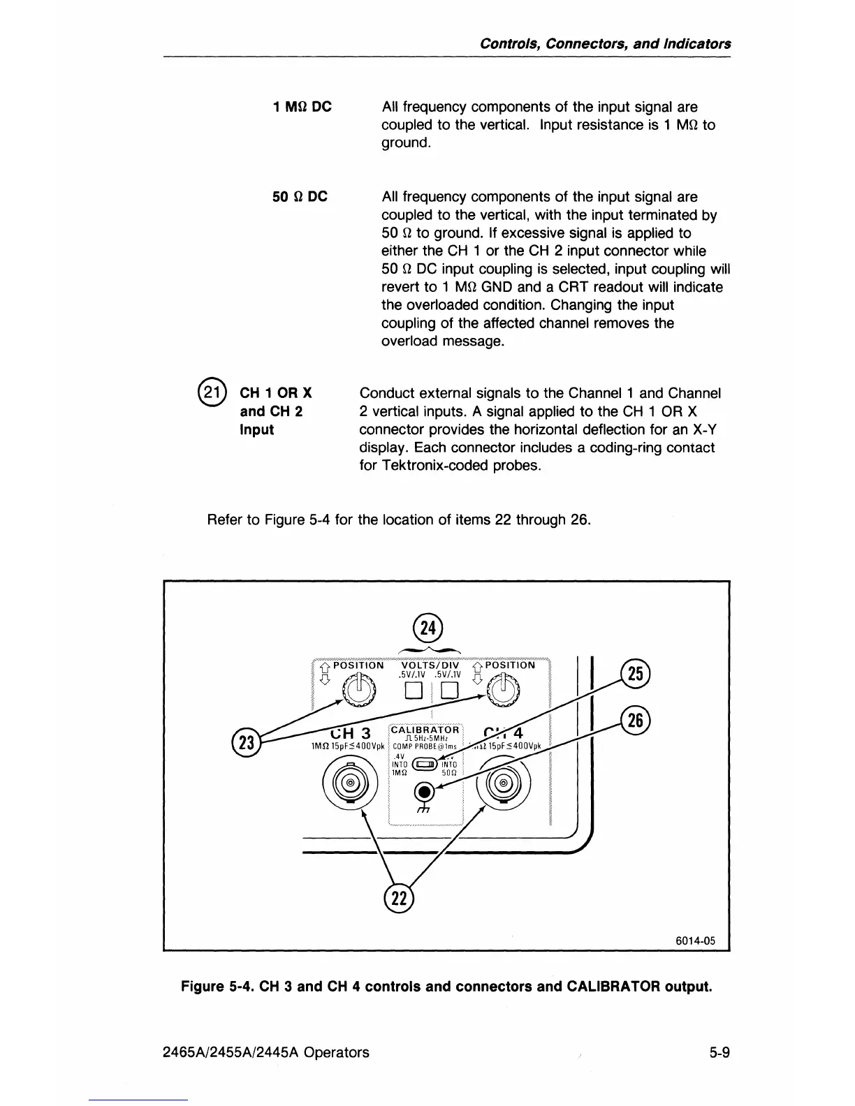
Refer to Figure 5-4 for the
location of items 22 through 26.
6014-05
Figure 5-4.
CH
3 and
CH
4 controls and connectors and CALIBRATOR output.
2465A/2455A/2445A Operators
5-9