6. Span and resolution bandwidth
7. Stop frequency
8. Reference marker
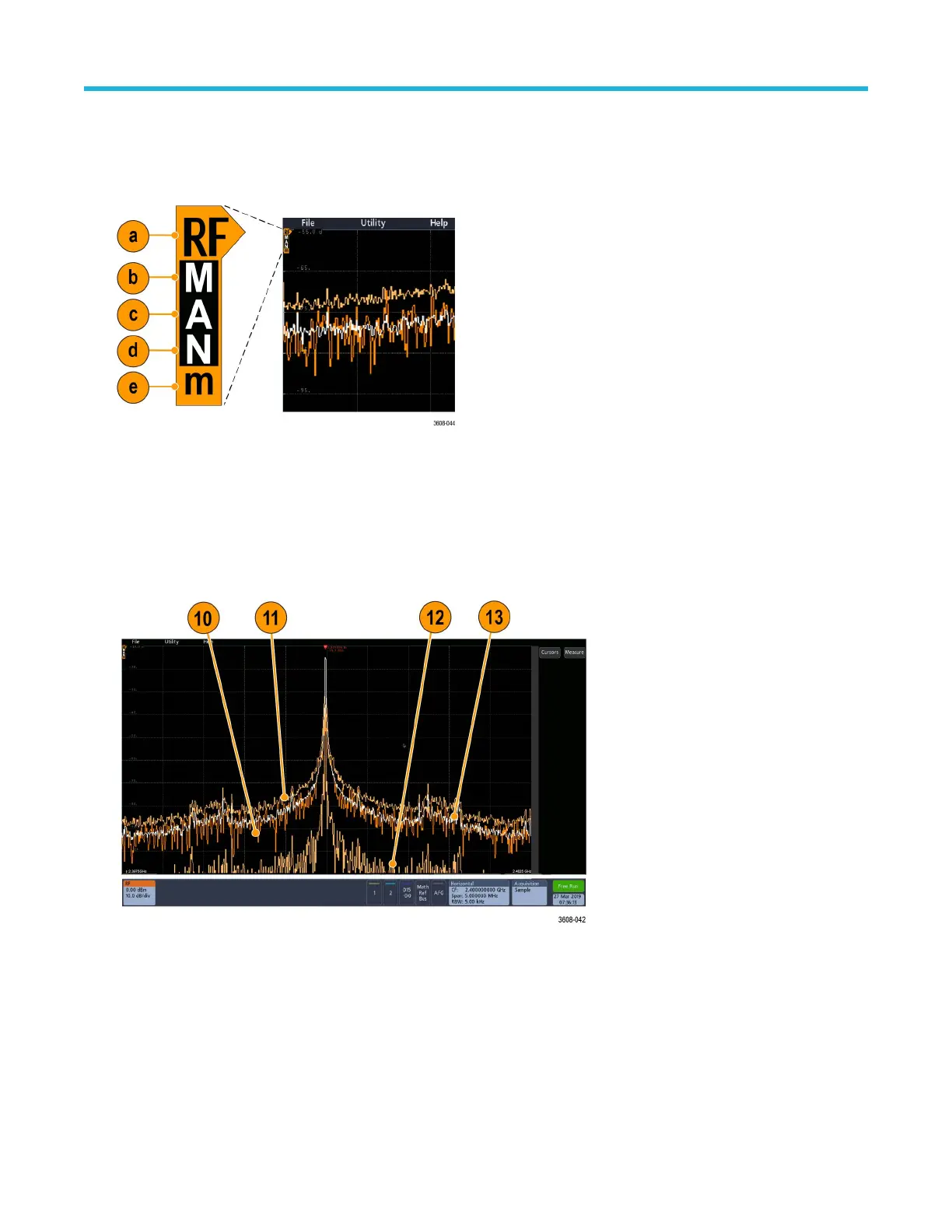
9. Displayed trace indicators
a. An RF trace indicator is placed at the Reference Level.
b. A capital M appears if the maximum trace is turned on.
c. A capital A appears if the average trace is turned on.
d. A capital N appears if the normal trace is turned on.
e. The small m appears if the minimum trace is turned on.
Orange highlighting indicates the currently selected trace. In the figures the small m, which stands for the minimum trace, is
highlighted. This indicates that the minimum trace is currently selected.
10. Normal trace: Each acquisition is discarded as new data is acquired.
1
1. Max hold trace: The maximum data values are accumulated over multiple acquisitions of the Normal trace.
12. Min hold trace: The minimum data values are accumulated over multiple acquisitions of the Normal trace.
13. Average trace: Data from the Normal trace is averaged over multiple acquisitions. This is true power averaging, which occurs before
the log conversion. Each power of 2 averaging reduces the displayed noise by 3 dB.
Getting acquainted with your instrument
3 Series Mixed Domain Oscilloscope Printable Help 48