Calibration-PS
501
0
Internal Adjustment Procedure
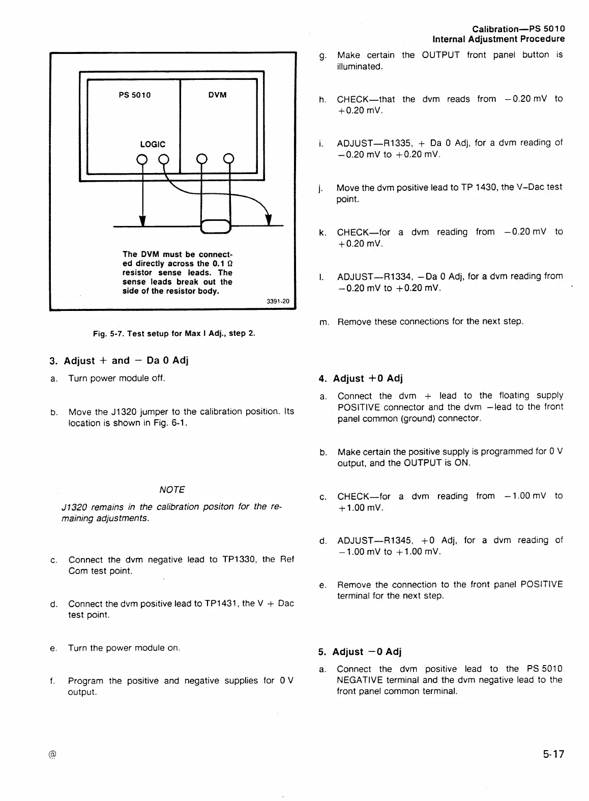
The
DVM
must be connect-
ed directly across the
0.1
Q
resistor sense leads. The
sense leads break out the
side of the resistor body.
3391
-20
PS
5010
LOGIC
Fig.
5-7.
Test setup for
Max
I
Adj., step
2.
DVM
3.
Adjust
+
and
-
Da
0
Adj
a. Turn power module off.
u
b.
Move the J1320 jumper to the calibration position. Its
location is shown in Fig. 6-1.
NOTE
J1320
remains
in
the calibration
positon
for the re-
maining adjustments.
Connect the dvrn negative lead to TP1330, the Ref
Com test point.
Connect the dvrn positive lead to TP1431, the V
+
Dac
test point.
Turn the power module on
Program the positive and negative supplies for 0 V
output.
g.
Make certain the OUTPUT front panel button is
illuminated.
h. CHECK-that the dvrn reads from -0.20
mV to
+0.20 mV.
i.
ADJUST-R1335,
+
Da 0 Adj, for a dvrn reading of
-
0.20 mV to +0.20 mV.
j.
Move the dvrn positive lead to TP 1430, the V-Dac test
point.
k.
CHECK-for a dvrn reading from -0.20 mV to
+
0.20 mV.
I.
ADJUST-R1334, -Da 0 Adj, for a dvrn reading from
-0.20 mV to +0.20 mV.
m. Remove these connections for the next step.
Adjust
+O
Adj
Connect the dvrn
+
lead to the floating supply
POSITIVE connector and the dvrn -lead to the front
panel common (ground) connector.
Make certain the positive supply is programmed for 0 V
output, and the OUTPUT is ON.
CHECK-for a dvrn reading from -1.00 mV to
+
1 .OO mV.
ADJUST-R1345,
+O
Adj, for a dvrn reading of
-
1 .OO mV to
+
1
.OO
mV.
Remove the connection to the front panel POSITIVE
terminal for the next step.
Adjust
-0
Adj
Connect the dvrn positive lead to the PS 5010
NEGATIVE terminal and the dvrn negative lead to the
front
ane el
common terminal.