Performance Conditions
The electrical and environmental performance limits, to-
gether with their related validation procedures, comprise
a
complete statement of the electrical and environmental per-
formance of a calibrated instrument.
The electrical characteristics in this specification are valid
only if the PS 5010 has been adjusted at an ambient tem-
perature between
+20°
C
and
+
30"
C.
The instrument
must be in a noncondensing environment whose limits are
described under the environmental part. Allow twenty min-
utes warm-up time for operation to specified accuracy; sixty
minutes after exposure to or storage in a high humidity (con-
densing) environment. Any conditions that are unique to a
particular characteristic are expressly stated as part of that
characteristic.
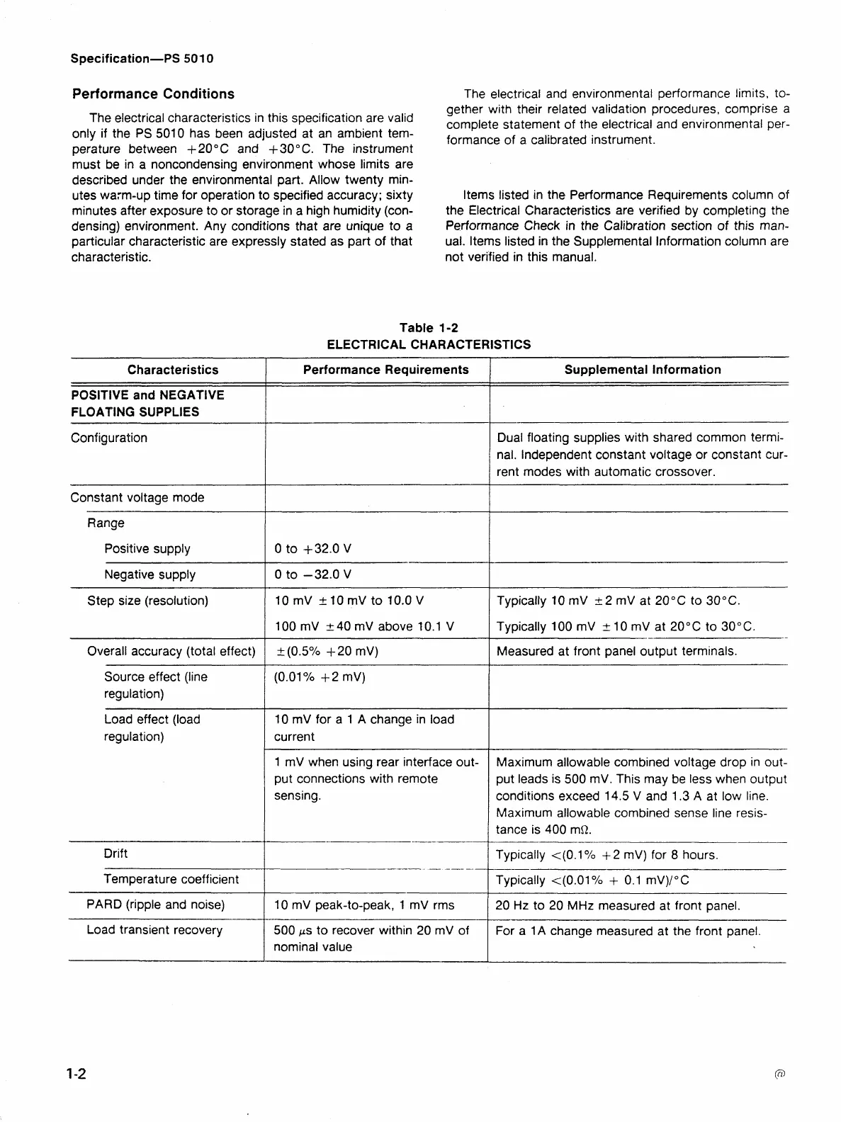
ltems listed in the Performance Requirements column of
the Electrical Characteristics are verified by completing the
Performance Check in the Calibration section
of
this man-
ual. ltems listed in the Supplemental Information column are
not verified in this manual.
Table
1-2
ELECTRICAL CHARACTERISTICS
Supplemental Information
Characteristics
Performance Requirements
POSITIVE and NEGATIVE
FLOATING SUPPLIES
Configuration
Dual floating supplies with shared common termi-
nal. Independent constant voltage or constant cur-
rent modes with automatic crossover.
Constant voltage mode
Range
Positive supply
Negative supply
Step size (resolution)
--
-
-
--
Typically 10 mV
+
2 mV at 20°C to 30°C.
Typically 1 00 mV
5
1 0 mV at 20"
C
to 30"
C
10 mV
k
10 mV to 10.0
V
100 mV
2
40 mV above 10.1 V
Overall accuracy (total effect) Measured at front panel output terminals.
--
-
Source effect (line
regulation)
Load effect (load
regulation)
10
mV for a 1 A change in load
current
1 mV when using rear interface out-
put connections with remote
sensing.
Maximum allowable combined voltage drop in out-
put leads is 500 mV. This may be less when output
conditions exceed 14.5 V and 1.3 A at low line.
Maximum allowable combined sense line resis-
tance is 400 mR.
Drift
Typically ((0.1
O/O
+
2 mV) for
8
hours.
Typically <(0.01%
+
0.1 mV)/"C
Temperature coefficient
PARD (ripple and noise)
10 mV peak-to-peak, 1 mV rms
20 Hz to 20 MHz measured at front panel.
Load transient recovery
500
ps
to recover within 20 mV of
nominal value
For a 1A change measured at the front panel