Operating Instructions-PS
SO
10
Fig.
2-5.
Graph of output characteristics for logic supply.
Load
Power
Supply
-
+
Q
0
0
Series-Connected Supplies
h
Power
Supply
-
+
OOQ
Fig.
2-6.
Supplies series connected.
L
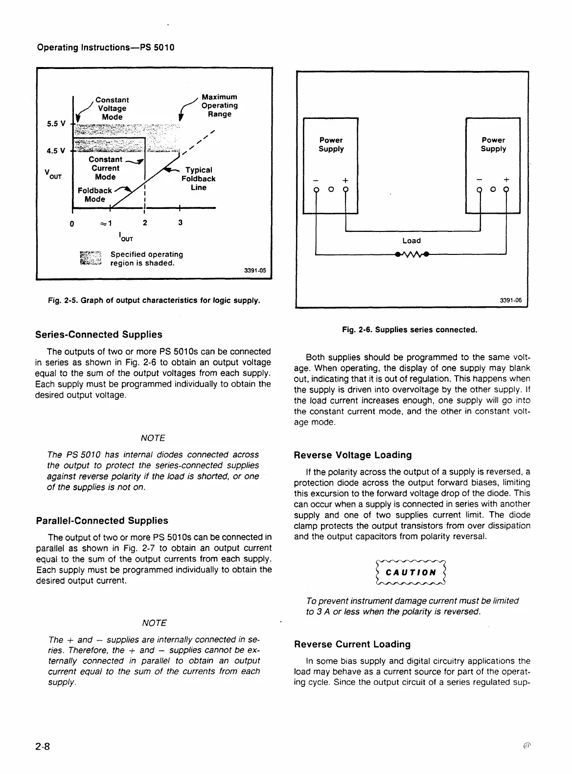
The outputs of two or more
PS
501 0s can be connected
in series as shown in Fig.
2-6
to obtain an output voltage
equal to the sum of the output voltages from each supply.
Each supply must be programmed individually to obtain the
desired output voltage.
NOTE
The
PS
501
0 has internal diodes connected across
the output to protect the series-connected supplies
against reverse polarity if the load is shorted, or one
of the supplies
is
not on.
Parallel-Connected Supplies
The output of two or more
PS
501
0s can be connected in
parallel as shown in Fig.
2-7
to obtain an output current
equal to the sum of the output currents from each supply.
Each supply must be programmed individually to obtain the
desired output current.
NOTE
The
+
and
-
supplies are internally connected in se-
ries. Therefore, the
+
and
-
supplies cannot be ex-
ternally connected in parallel to obtain an output
current equal to the sum of the currents from each
supply.
Both supplies should be programmed to the same volt-
age. When operating, the display of one supply may blank
out, indicating that it is out of regulation. This happens when
the supply is driven into overvoltage by the other supply. If
the load current increases enough, one supply will go into
the constant current mode, and the other in constant volt-
age mode.
Reverse Voltage Loading
If the polarity across the output of
a
supply is reversed, a
protection diode across the output forward biases, limiting
this excursion to the forward voltage drop of the diode. This
can occur when a supply is connected in series with another
supply and one of two supplies current limit. The diode
clamp protects the output transistors from over dissipation
and the output capacitors from polarity reversal.
CAUTION
a
To prevent instrument damage current must be limited
to
3
A
or less when the polarity is reversed.
Reverse Current Loading
In some bias supply and digital circuitry applications the
load may behave as a current source for part of the operat-
ina cvcle. Since the out~ut circuit of a series reaulated SUD-