Operating Instructions-PS
501
0
1.
Obtain a corrugated carton having inside dimensions
of no less than six inches more than the instrument
dimensions; this will allow for cushioning. Use a car-
ton having a test strength of at least 200 pounds.
2.
Surround the instrument with protective polyethylene
sheeting.
3. Cushion the instrument on all sides by tightly packing
dunnage or urethane foam between carton and instru-
ment, allowing three inches on all sides.
4. Seal carton with tape or industrial staples.
Power
Up
Conditions (Self Test)
At power up, the PS 5010 microprocessor performs a
diagnostic routine to check the functionality of the ROM and
RAM. If no internal error is found, the instrument enters the
Local State (LOCS) with default settings as shown in Table
2-1. The SRQ line on the GPlB is also asserted.
Table
2-1
POWER ON SETTINGS
The instrument goes to the following settings at power
on and when the INIT command is executed.
Function
Positive supply voltage
Positive supply current
Negative supply voltage
Negative supply current
Logic supply voltage
Logic supply current
Floating supply output
Logic supply output
Positive regulation interrupt
Negative regulation interrupt
Logic regulation interrupt
Request for service
User request
Device trigger
-.
-
--
-
.
-
-
-
Condition
0.0 Volts
0.4 Amps
0.0 Volts
0.4 Amps
5.0 Volts
1.0 Amps
OFF
OFF
OFF
OFF
OFF
ON
OFF
OFF
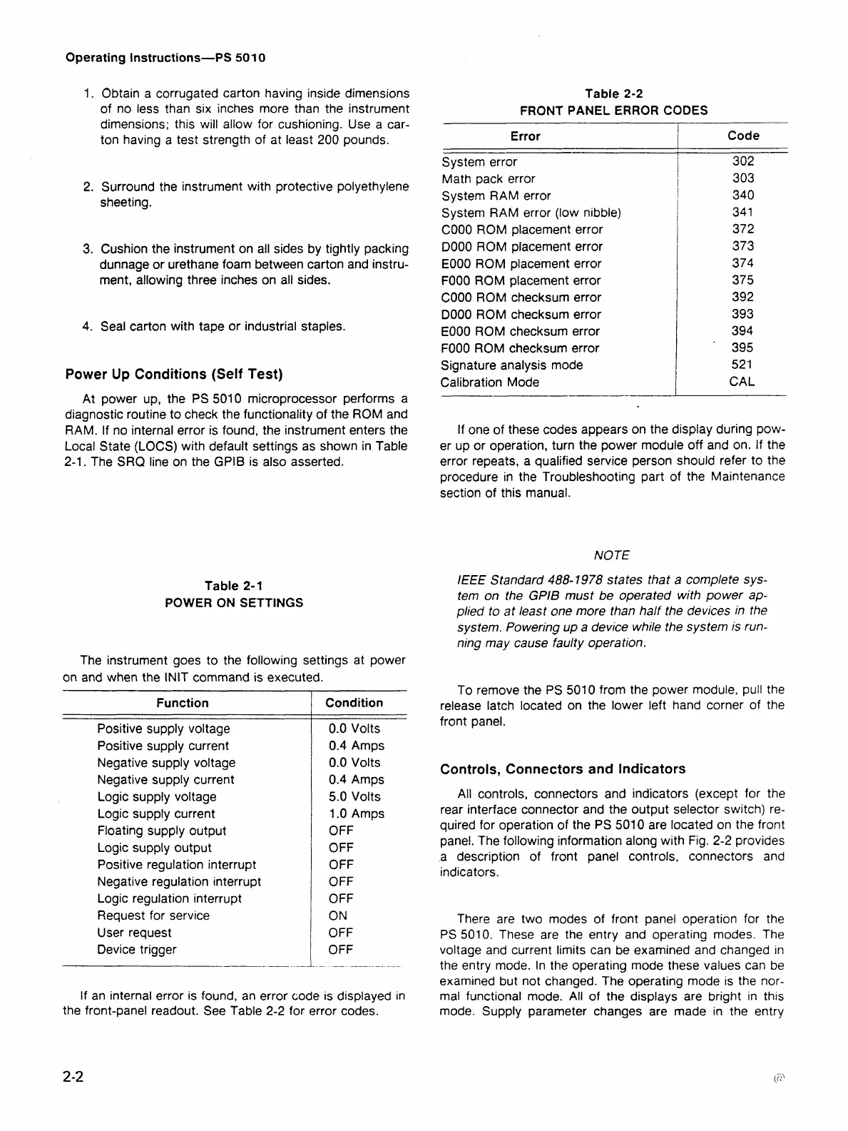
If an internal error is found, an error code is displayed in
the front-panel readout. See Table 2-2 for error codes.
Table
2-2
FRONT PANEL ERROR CODES
Error
System error
Math pack error
System RAM error
System RAM error (low nibble)
COOO ROM placement error
DO00 ROM placement error
EOOO ROM placement error
FOOO ROM placement error
COOO ROM checksum error
DO00 ROM checksum error
EOOO ROM checksum error
FOOO ROM checksum error
Signature analysis mode
Calibration Mode
-----
Code
302
303
340
34
1
372
373
374
375
392
393
394
395
52
1
CAL
If one of these codes appears on the display during pow-
er up or operation, turn the power module off and on. If the
error repeats, a qualified service person should refer to the
procedure in the Troubleshooting part of the Maintenance
section of this manual.
NOTE
I€€€
Standard
488-1978
states that
a
complete sys-
tem on the
GPlB
must be operated with power ap-
plied to at least one more than half the devices in the
system. Powering up a device while the system is run-
ning may cause faulty operation.
To remove the PS 501 0 from the power module, pull the
release latch located on the lower left hand corner of the
front panel.
Controls, Connectors and Indicators
All controls, connectors and indicators (except for the
rear interface connector and the output selector switch) re-
quired for operation of the PS 5010 are located on the front
panel. The following information along with Fig. 2-2 provides
a description of front panel controls, connectors and
indicators.
There are two modes of front panel operation for the
PS
5010. These are the entry and operating modes. The
voltage and current limits can be examined and changed
rn
the entry mode. In the operating mode these values can be
examined but not changed. The operating mode is the nor-
mal functional mode. All of the displays are bright in this
mode. Supply parameter changes are made in the entry