Operating Instructions-PS
501
0
Power
Supply
-
COM
+
Power
Supply
-
COM
+
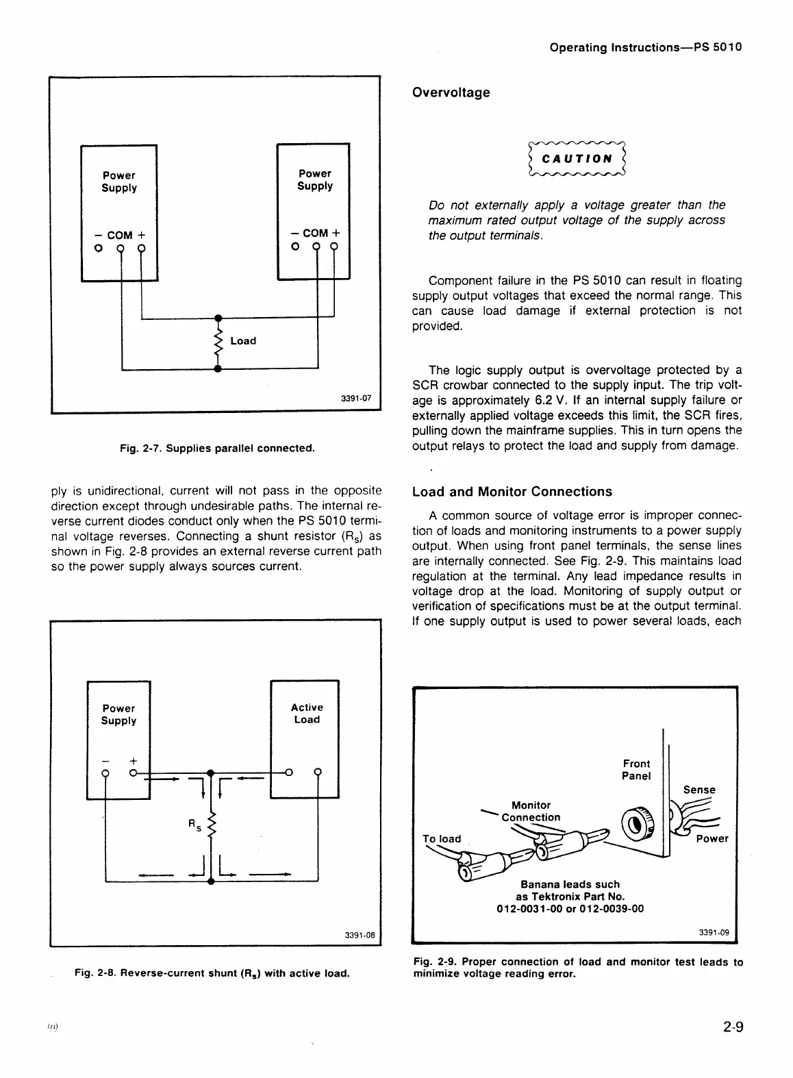
Fig. 2-7. Supplies parallel connected.
ply is unidirectional, current will not pass in the opposite
direction except through undesirable paths. The internal re-
verse current diodes conduct only when the PS 5010 termi-
nal voltage reverses. Connecting a shunt resistor
(R,)
as
shown in Fig.
2-8
provides an external reverse current path
so the power supply always sources current.
Power
Supply
-
+
Active
J
Fig.
2-8.
Reverse-current shunt (R,) with active load.
Overvoltage
CAUTION
D
Do not externally apply a voltage greater than the
maximum rated output voltage of the supply across
the output terminals.
Component failure in the
PS
5010 can result in floating
supply output voltages that exceed the normal range. This
can cause load damage if external protection is not
provided.
The logic supply output is overvoltage protected by a
SCR crowbar connected to the supply input. The trip volt-
age is approximately
6.2
V.
If
an internal supply failure or
externally applied voltage exceeds this limit, the SCR fires,
pulling down the mainframe supplies. This in turn opens the
output relays to protect the load and supply from damage.
Load and Monitor Connections
A
common source of voltage error is improper connec-
tion of loads and monitoring instruments to a power supply
output. When using front panel terminals, the sense lines
are internally connected. See Fig.
2-9.
This maintains load
regulation at the terminal. Any lead impedance results in
voltage drop at the load. Monitoring of supply output or
verification of specifications must be at the output terminal.
If one supply output is used to power several loads, each
Monitor
Banana leads such
as Tektronix Part No.
0
1
2-003
1
-00 or 0
1
2-0039-00
Fig. 2-9. Proper connection of load and monitor test leads to
minimize voltage reading error.